Autohelm
AutohelmAutohelm
Autohelm
SeaTalk Service Manual
2
1. Control Unit PCB Circuit description
Fig. 4. Circuit Diagram
Fig. 5. PCB Assembly/Parts List
1.1 Power supply
Incoming power is routed to the PCB via PL1 and SKT1. Dl and D2 protect against
reverse connection of the supply. IC1 is a 5v regulator and can also reset the
microprocessor, via TR1, should the supply voltage fall below 6V.
1.2 Microprocessor and program memory
IC6 is an Intel 80C32 microprocessor. It can access up to 32k bytes of program
memory (IC5) via the latch IC4. A clock signal for the microprocessor is provided by
an 11MHz ceramic resonator (XL1), and associated capacitors CIS and C16.
Capacitors C17, C18 and C19 provide decoupling.
1.3 LCD and Display driver
The LCD is a Nautech custom part. The display is driven by a Hitachi Led driver (IC3)
deriving its drive voltages from resistor chain R27-R30 and VR1. Communication to
the microprocessor is via a 4 bit parallel bus (DB4 to DB7) and the three control lines
E,R/W and RS. Capacitors C8 and C10 provide decoupling and resistor R26 the
clock signal for IC3.
1.4 Negative Rail Generator
A negative voltage rail is required by the LCD display and is generated by a switching
regulator formed by TR6,D5 and D6. A 4.8kHz waveform is generated from the
microprocessor P3.4 (pin no. 16). This drives a charge pump, via transistor TR16,
pumping charge from C20 via D6 to C21. The negative rail is then stabilised by D5
and R49.
1.5 N.M.E.A Interface
NMEA data is fed to the control unit via PL2 and isolated from the rest of the circuit
using the opto-isolator (IC7). Diode D3 provides input reverse connection protection
and resistor R15 is tuned to give the desired bandwidth of operation. The output from
IC7 is connected to the microprocessor Port P3.2 (pin 14). Capacitor C7 provides
decoupling.
1.6 Seatalk Bus Transmit and Receive
Seatalk transmit and receive circuitry consists of TR9, 10, 11 ,12, 13, 14 and 15 and
their associated components. Data transmission is at 4800 baud with a low start bit
and line idling high. TR9 and TR13 provide high and low output respectively, whilst
TR14 and R45/46 give overload protection to Trl3 in the event of misconnection.
TR10 and TR11 allow the microprocessor to monitor its own transmissions and also
to receive data from other units on the bus.
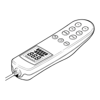
1.7 Keypad operation
The 10 button keypad is interfaced to the microprocessor via 2 dual input multiplexer
IC's.
 Loading...