Do you have a question about the Raymarine ST7000 and is the answer not in the manual?
Manual for Autohelm Inboard Autopilots covering ST6000 and ST7000 systems.
Procedures for servicing the ST7000 basic autopilot system.
Overview of the ST7000 system manual contents and scope.
Details the modular nature and components of the ST7000 autopilot system.
Covers operation and calibration procedures for the ST7000 system.
Explains how to operate the ST7000 autopilot in various modes.
Provides guidance on response levels, track, trim, and rudder gain.
Information relevant to sailing vessels, including Autotack and Wind Trim.
Details recommended settings and mode selection/exit for calibration.
Procedure to correct the fluxgate compass for magnetic fields.
Lists common problems, their causes, and solutions for the ST7000 system.
Covers interfacing, inverted data, unit conversion, and alarms.
General advice for performing a service visit to a vessel.
Outlines the diagnostic procedure to follow during a service visit.
Procedures for servicing the Z082 Control Unit.
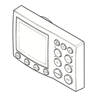
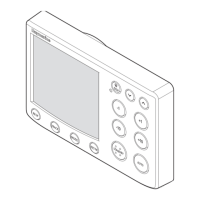
Describes the Z082 Control Unit, its compatibility, and technology.
Step-by-step guide on how to dismantle the Z082 Control Unit.
Step-by-step guide on how to reassemble the Z082 Control Unit.
Procedure to adjust the LCD contrast for optimal legibility.
Steps for performing a functional test on the Z082 Control Unit.
Details product changes and serial numbers for the Z082 Control Unit.
Outlines software versions and changes for the Z082 Control Unit.
List of spare parts and their catalogue numbers for the Z082 Control Unit.
Technical details including circuit descriptions and component functions.
Procedures for servicing the Z083 (12V) and Z084 (24V) Course Computers.
Describes the ST7000 course computer and power amplifier components.
Steps for dismantling the course computer and power amplifier PCBs.
Steps for reassembling the course computer and power amplifier PCBs.
Procedure for functionally testing the course computer.
Product history of the Z083 and Z084 Course Computers.
Software history for the Z083 and Z084 Course Computers.
List of spare parts for the Z083 and Z084 Course Computers.
Technical details including circuit descriptions and component functions.
Procedures for servicing the ST6000 System.
Overview of the ST6000 system manual contents and scope.
Describes the modular ST6000 autopilot system and compatible drive units.
Covers operation and calibration procedures for the ST6000 system.
Explains how to operate the ST6000 autopilot in various modes.
Information relevant to sailing vessels, including Autotack and Wind Trim.
Guidance on response, track, waypoint advance, trim, and rudder gain.
Details recommended settings and mode selection/exit for calibration.
Procedure to correct the fluxgate compass for magnetic fields on the ST6000.
Lists common problems, causes, and solutions for the ST6000 system.
Covers interfacing, data format, units, and alarms for track control.
General advice for performing a service visit to a vessel.
Procedures for servicing the ST6000 Control Unit (Z124).
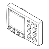
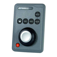
Describes the Z124 Control Unit and its compatibility.
Steps to dismantle the Z124 Control Unit.
Steps to reassemble the Z124 Control Unit.
Procedure to adjust the LCD contrast on the Z124 Control Unit.
Functional test procedure for the Z124 Control Unit.
Product history of the Z124 Control Unit.
Software history for the Z124 Control Unit.
List of spare parts for the Z124 Control Unit.
Technical details including circuit descriptions and component functions.
Procedures for servicing the ST6000 Course Computer (Z123).
Describes the ST6000 Course Computer and its power amplifier.
Steps for disassembling the ST6000 Course Computer.
Steps for reassembling the ST6000 Course Computer.
Procedure for functionally testing the ST6000 Course Computer.
Product history of the ST6000 Course Computer.
Software history for the ST6000 Course Computer.
List of spare parts for the ST6000 Course Computer.
Technical details including circuit descriptions and component functions.
Procedures for servicing the Type CR Interface Box (Z085).
Describes the Type CR Interface Box and its use with course computers.
Procedure for functionally testing the Type CR Interface Box.
Notes on using the Type CR Interface Box with non-Autohelm power packs.
Technical details including circuit descriptions and component functions.
Procedures for servicing the Rudder Reference Transducer (Z131).
Describes the Z131 Rudder Reference Transducer and its function.
How to functionally test the Z131 Rudder Reference Transducer.
Procedures for servicing the Fluxgate Compass Transducer (Z130).
Describes the Z130 Fluxgate Compass Transducer and its components.
How to functionally test the Z130 Fluxgate Compass Transducer.
Importance of siting and correcting magnetic deviation for the Z130 Fluxgate.
Describes the Z105 Fluxgate Compass Transducer and its replacement.
How to functionally test the Z105 Fluxgate Compass Transducer.
Importance of siting and correcting magnetic deviation for the Z105 Fluxgate.
Procedures for servicing the Rudder Reference Transducer (Z060).
Describes the Z060 Rudder Reference Transducer and how to test it.
Procedure to reset the centre position of the Z060 Rudder Reference Transducer.
Product history for the Z060 Rudder Reference Transducer.
Procedures for servicing Z080 Masthead and Z087 Pushpit Windvane Transducers.
Describes the Z080 and Z087 Windvane Transducers and their compatibility.
How to test the Z080 Masthead Windvane Transducer.
How to test the Z087 Pushpit Windvane Transducer.
Product history for the Z080 Masthead Transducer.
Spare parts list for the Z080 Masthead Transducer.
Procedures for servicing Linear Drive Units.
Introduction to the Linear Drive Unit's construction and operation.
Visual inspection guidelines before servicing Linear Drive Units.
Steps for dismantling Linear Drive Units.
Steps for reassembling Linear Drive Units.
Notes on operating Linear Drive Units with non-Autohelm autopilots.
Functional test procedure for Linear Drive Units.
Product history for Type 2 Long Stroke Linear Drive Actuators.
Product history for Type 1 Linear Drive Actuators.
Product history for Type 2 Short Stroke Linear Drive Actuators.
Spare parts list for Linear Drive Units.
Procedures for servicing Rotary Drive Units.
Introduction to the Rotary Drive Unit's construction and operation.
Steps for dismantling Rotary Drive Units.
Steps for reassembling Rotary Drive Units.
Notes on operating Rotary Drive Units with non-Autohelm autopilots.
Functional test procedure for Rotary Drive Units.
Spare parts list for Rotary Drive Units.
Service procedures for the Type '0' Piston Pump (Z081).
Service procedures for Constant Running Power Packs.
Service procedures for Reversing Gear Pumps.
Introduction to the three types of hydraulic drive units.
Steps for dismantling and reassembling Constant Running Power Packs.
Procedures for cleaning and reassembling Reversing Gear Pumps.
Steps for reinstalling and bleeding the Type '0' Piston Pump.
Procedures for servicing the Inboard/Outboard Drive Unit (Z088).
Introduction to the I/O Drive Unit and its applications.
Procedures for motor replacement in the I/O Drive Unit.
Functional test procedure for the I/O Drive Unit motor and clutch.
| Brand | Raymarine |
|---|---|
| Model | ST7000 |
| Category | Marine Equipment |
| Language | English |