Do you have a question about the Raymarine T150 and is the answer not in the manual?
Overview of the Course Computer's function, components, and purpose.
Details the four different versions of the Course Computer and their key differences.
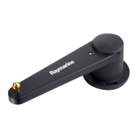
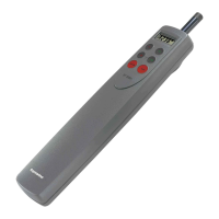
Lists spare parts and accessories for the 150/150G models.
Visual breakdown of the 150/150G Course Computer parts for identification.
Lists spare parts and accessories for the 400/400G models.
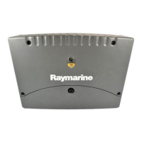
Visual breakdown of the 400/400G Course Computer parts for identification.
Illustrates available spare parts packs for all models for easier ordering.
Explains how to perform basic functional tests to aid fault diagnosis.
Outlines essential visual checks to perform before applying power to the unit.
Procedure for measuring resistance of specific resistors for test purposes.
Instructions on verifying the correct connection of the rate gyro plug.
Guidance on visually inspecting the relay contacts and surrounding components.
Describes the SIL pad and its function, and how to check its integrity.
Guides through step-by-step diagnostic tests for comprehensive fault finding.
Verifies correct voltage levels at various test points on the PCB.
Verifies compass heading and rudder bar display for Seatalk communication function.
Tests the internal rate gyro by measuring voltage changes during rotation.
Checks compass accuracy and heading display by rotating the unit.
Verifies rudder reference input and display movement for correct operation.
Tests clutch engagement in AUTO mode by measuring output voltage.
Tests clutch engagement in STANDBY mode by measuring output voltage.
Tests motor direction and speed control via the H-Bridge circuit.
Verifies NMEA data input and output for proper communication functionality.
Tests the kill switch functionality by observing unit shutdown and power-up.
Checks if calibration settings are stored correctly by verifying drive type changes.
Lists all necessary tools for safely disassembling and reassembling the unit.
Step-by-step instructions for safely taking the Course Computer apart.
Step-by-step instructions for correctly putting the Course Computer back together.
Procedure for removing and installing the GyroPlus yaw sensor module.
Instructions on recalibrating the autopilot after sensor installation.
Identifies and describes key test points on the Course Computer PCB for diagnostics.
Details the primary functional blocks and their operation within the circuit.
Explains the power supply circuitry and its variations across different models.
Describes the H-Bridge circuit responsible for motor control and speed.
Explains the spool valve control mechanism and its current sensing.
Details the clutch output control and its current sensing mechanism.
Describes the operation and interface of the fluxgate compass sensor.
Explains the internal and external rate gyro signal processing and measurement.
Details the power supply and signal path for an external gyro sensor.
Describes the power supply and signal path for the internal gyro sensor.
Explains the rudder transducer connection and signal amplification stages.
Describes the two NMEA input channels and their specific configurations.
Describes the two NMEA output channels and their specific configurations.
Explains the SeaTalk circuit functionality, level shifting, and isolation.
Details the microcontroller used, its architecture, and key peripherals.
Describes the watchdog timer's role in monitoring microcontroller health.
Explains the process and circuitry for programming the unit's flash memory.
Describes the storage of calibration data and other critical settings.
Lists all terminal blocks, their labels, signals, and connection directions.
References the appendix for detailed circuit diagrams and PCB layouts.
Lists surface mount PCB components with part numbers and PCB references.
Lists PCB components specific to the 150/150G conventional mount version.
Lists PCB components specific to the 400/400G conventional mount version.
Introduces software upgrade capabilities via the NMEA port and PC connection.
Lists the necessary PC hardware and software for performing upgrades.
Details the cable connection requirements between the Course Computer and PC.
Provides a step-by-step guide for performing the software upgrade process.
| Brand | Raymarine |
|---|---|
| Model | T150 |
| Category | Autopilot System |
| Language | English |