Installation
Page 7
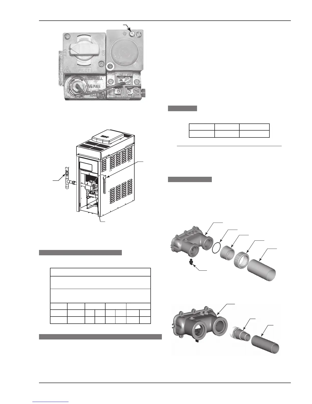
Figure 9C. Honeywell MV Gas Valve.
ELECTRONIC IGNITION GAS VALVES
Figure 10. Location of Gas Pressure Adjustment.
PIPE SIZING FOR GAS CONNECTIONS
Table 5. Maximum Equivalent Pipe Length.
WATER CONNECTIONS
The heater requires water flow and positive pressure to
fire and operate properly. It must therefore be installed down-
stream of the discharge side of the filter pump. A typical
installation is plumbed as follows:
Maximum Equivalent Pipe Length
Natural Gas 1000 BTU/FT3 0.60
Specific Gravity @ 0.5 in. WC Pressure Drop
Propane Gas 2500 BTU/FT3 1.53
Specific Gravity @ 0.5 in. WC Pressure Drop
Input 1/2” 3/4” 1”
Model (KBTU) N P N P N P
130A 130 15 35 60 145 200 500
1. The inlet side of the filter is plumbed directly to the dis-
charge side of the filter pump;
2. The outlet side of the filter is then plumbed to the inlet of
the heater; and
3. The outlet of the heater is plumbed to the return line to
the pool or spa. The pump, filter and heater are thus
plumbed in series.
Plumbing from the heater back to the pool or spa must
not have any valves or restriction that could prevent flow
when the pump is operating.
Heater must be located so that any water leaks will not
damage the structure of adjacent area. PVC pipe may be
glued directly into optional or field-supplied header unions.
FLOW RATES
Table 6. Water Flow Rates.
*NOTE: When flow rates exceed maximum 100
GPM an external auxiliary bypass valve is required.
See External Auxiliary Bypass Valve section for
details.
POLYMER HEADERS
Before attaching the optional 2-inch unions to the In/Out
header, make sure the O-rings are properly seated in the
grooves. Use AquaLube or equivalent non-petroleum-based
lubricant on the O-ring. Hand tighten the unions. Glue PVC
piping directly to the unions.
Figure 11. Optional In/Out Header for 2" Installation.
Figure 12. In/Out Header for 1-1/2" or 1-1/4" Hose Connection.
 Loading...