12
(field supplied)
(
field supplied)
(field supplied)
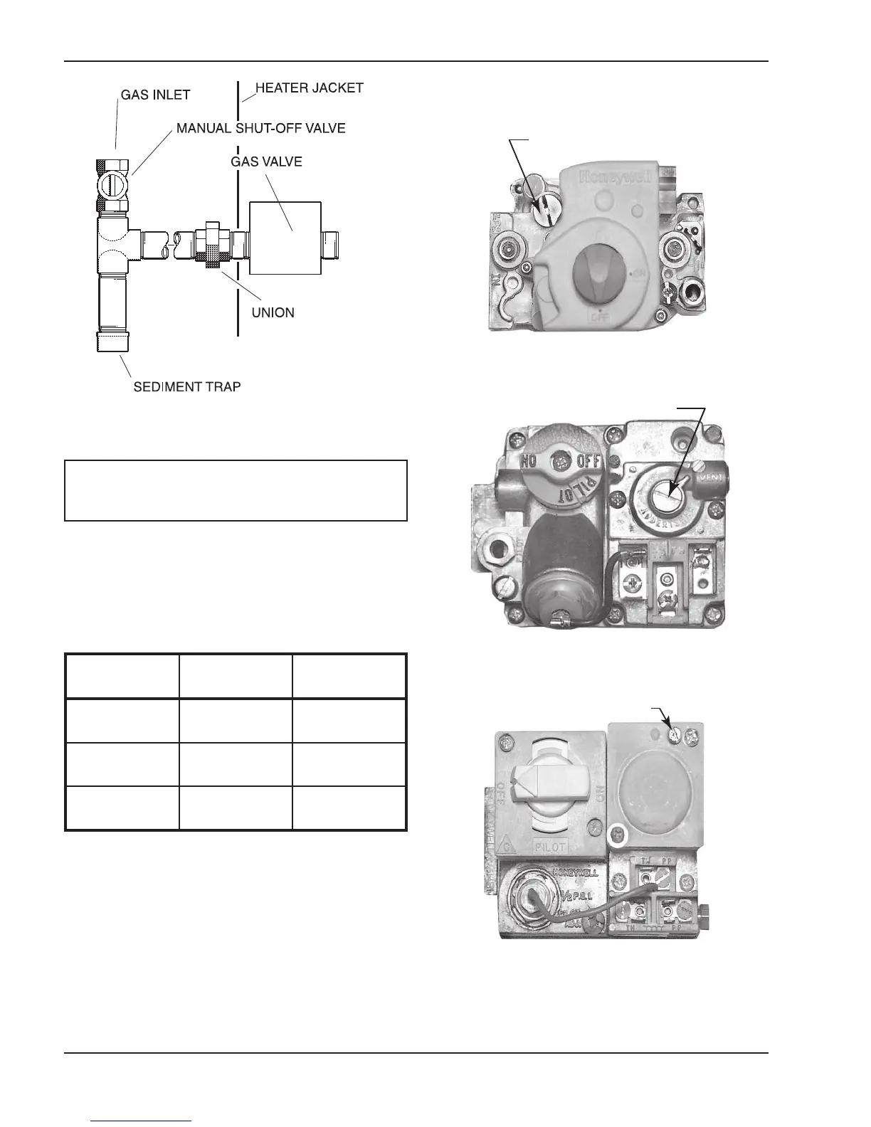
Fig. 9: Gas Line Sediment Trap
NOTE: Do not use Teflon tape on gas line pipe
thread. A flexible pipe sealant suitable for LP gases
is recommended.
Gas Pressure Regulator
If adjustment is needed, remove seal and turn adjust-
ment screw clockwise to increase pressure or
counter-clockwise to decrease pressure.
Gas Pressure* Natural Gas Propane Gas
Max. Inlet
(static)
10.5 in. WC 13 in. WC
Min. Inlet
(dynamic)
7 in. WC 11 in. WC
Manifold Gas
(dynamic)
3.5 in. WC 10 in. WC
*Static means without heater operating, dynamic refers to heater
operating.
Table D: Gas Pressure
Gas Pressure Adjustment Locations
Gas Pressure Adjustment
A.
Gas Pressure Adjustment
B.
C.
Gas Pressure Adjustment
Fig. 10A: Honeywell DSI VR 8205 Gas Valve
Fig. 10B: Robertshaw MV Gas Valve
Fig. 10C: Honeywell MV Gas Valve