Do you have a question about the RBH Sound UNC100 and is the answer not in the manual?
| Brand | RBH Sound |
|---|---|
| Model | UNC100 |
| Category | Controller |
| Language | English |
Details various types of input circuits supported by the UNC100, from low to high security.
Describes the default applications for input configurations, such as General Purpose or Door Contact.
Explains different operating modes for access points like High Security, Unlocked, and Tamper.
Requirements for ULC-S319-05 III compliance, including wiring through metal conduit and protected mounting.
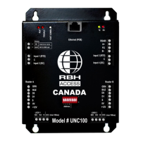
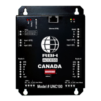
Explains the function of various diagnostic LEDs on the panel for system status.
Describes the tamper detection mechanism using JP1, noting normal and alarm states.
Configuration of power terminals for input or output supply, including POE considerations.
Details the communication interfaces available: RS485 port and Ethernet 10/100 interface.
Explains how DIP switches control the device's address and serial port baud rate.
Illustrates the RS485 wiring connection from a PC to the UNC100.
Specifies twisted pair, shielded cable (18-22 AWG) and max length for RS485 connections.
Diagram showing connection via a LAN switch, with default IP address mentioned.
Describes Wiegand interfaces, power, tamper input, and LED/beeper outputs for readers.
Diagram illustrating the connection of a RC-2 to 12-Volt reader.
Details the two form C relays and two open collector outputs available for programming.
Cautionary advice on switching inductive loads and using diodes for suppression.
User-controlled outputs activated by defined links and schedules.
Configuration for magnetic locks, fail-safe operation, and power failure behavior.
Output that activates on forced door entry or reader tamper detection.
Details the UNC100's 4 supervised inputs and their states (Restore, Alarm, Trouble, Illegal).
Explains seven input circuit types, including resistor configurations for security levels.
Lists default applications for inputs like General Purpose, RTE, and Door Contact.
Describes a circuit type used for mixed normally open and normally closed contacts.
Details the RTE input for unlocking doors via push button or motion detector.
Explains how DC inputs monitor door state for alarms like forced entry.
Defines modes like High Security, Unlocked, Tamper, Lockout Alarm, and Door Held Open.
Lists technical specifications including power, memory, processor, dimensions, and environmental limits.
Details cable types and lengths for Ethernet, RS485, and input/output port circuit loops.