35
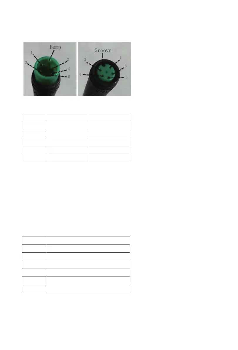
Connection Layout
Connector wire sequence
Display-side connector mating connector
Wire sequence table
Wire No. Color Function
1 Red(VCC) +
2 Blue(K) Lock
3 Black(GND) -
4 Green(RX) RX
5 Yellow(TX) TX
• Some wire use the water-proof connector, users can not see the inside color.
XIV-9. Operation Cautions
• Be cautious. Don’t attempt to disconnect the connector when battery is on power.
• Try to avoid hitting.
• Do not modify system parameters to avoid parameters disorder.
• Make the display repaired when error code appears.
NOTE: *This manual instruction is a universal version for DISPLAY KD986. Some versions
of this display may be different from specication to specication as to the software.
Please always refer to an actual version.
Attachedlist1:Errorcodedenition
Error code Denition
21 Current Abnormality
22 Throttle Abnormality
23 Motor Abnormality
24 Motor Hall Signal Abnormality
25 Brake Abnormality
30 Communication Abnormality
 Loading...