Service Manual 9. Disassembly and Assembly
330
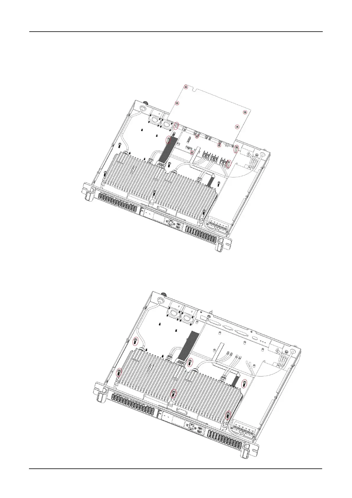
Step 3 Remove the four screws locking the cover for the rear board PCB and take the cover
out. Remove the screws, studs, and cables on the rear board. Then take the rear
board PCB out.
Step 4 Remove the six screws fixing the aluminum shielding box for the TX and RX modules
and detach the RF cables. Then take the shielding box out.