RIGGING PROCEDURE
Installation and setup should only be carried out by qualified and authorized personnel observing the valid national Rules for
the Prevention of Accidents (RPA).
It is the responsibility of the person installing the assembly to ensure that the suspension/fixing points are suitable for the
intended use.
Always carry out a visual and functional inspection of the items before use. In the event of any doubt as to the proper
functioning and safety of the items, these must be withdrawn from use immediately.
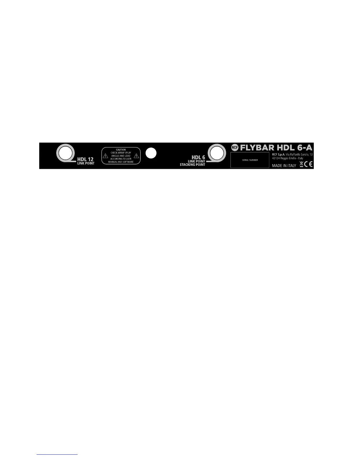
WARNING - The steel wires between the locking pins of the cabinets and rigging components are not intended to carry any
load. The cabinet’s weight must only be carried by the Front and Splay/Rear links in conjunction with the front and rear rigging
strands of the loudspeaker cabinets and the Flying frame. Ensure all Locking pins are fully inserted and securely locked before
lifting any load.
In the first instance use HDL 6-A Shape Designer software to calculate the proper set up of the system and to check the safety
factor parameter.
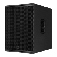
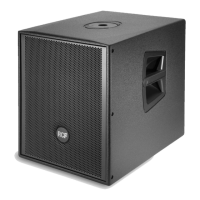
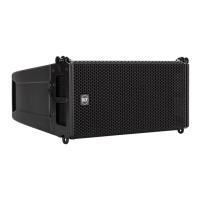
The HDL6 flybar allows the suspension of HDL6-A and HDL12-AS.
 Loading...