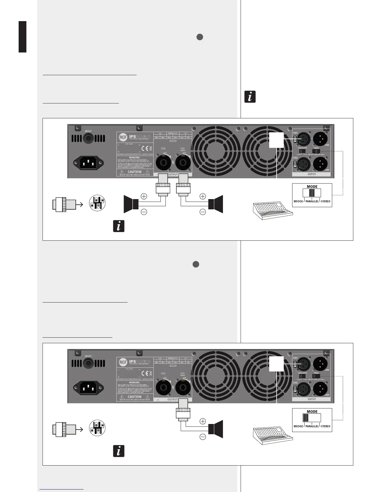
PARALLEL (MONO) MODE
Make sure the amplier is switched off before setting the MODE switch
11
to
PARALLEL.
In mono mode, both channels are linked to input 1 (therefore receiving the same signal).
Each front panel level control affects its respective output, allowing you to set (if
necessary) different levels.
Minimum load impedance is 4 Ω per output.
Loudspeakers shall be connected to the outputs 1 and 2.
note that only the amplIfIer Inputs are lInked In parallel. thIs Is not an output parallel mode.
never connect both outputs In parallel!
BRIDGE MODE
Make sure the amplier is switched off before setting the MODE switch
11
to BRIDGE.
In ‘bridge’ (mono) mode, both amplier channels work with the same input signal, but with
inverse phases. The result is a doubling of the output voltage in order to get a double power
(on a double impedance load).
Connect the CH 1 input and output only.
The output level is adjusted only by the channel 1 front panel control.
Pay attention to the output SPEAKON wiring: pin 1+ positive, pin 2+ negative.
Minimum load impedance is: 8 Ω.
MIXER
1+
2+
1–
2–
WARNING: TURN OFF THE AMPLIFIER
BEFORE CHANGING MODE!
1+
1–
1+
1–
USE CH1
INPUT
ONLY
MIXER
1+
2+
1–
2–
WARNING: TURN OFF THE AMPLIFIER
BEFORE CHANGING MODE!
1+
2+
USE CH1 OUTPUT
ONLY
USE CH1
INPUT
ONLY