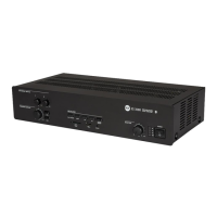
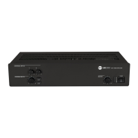
7
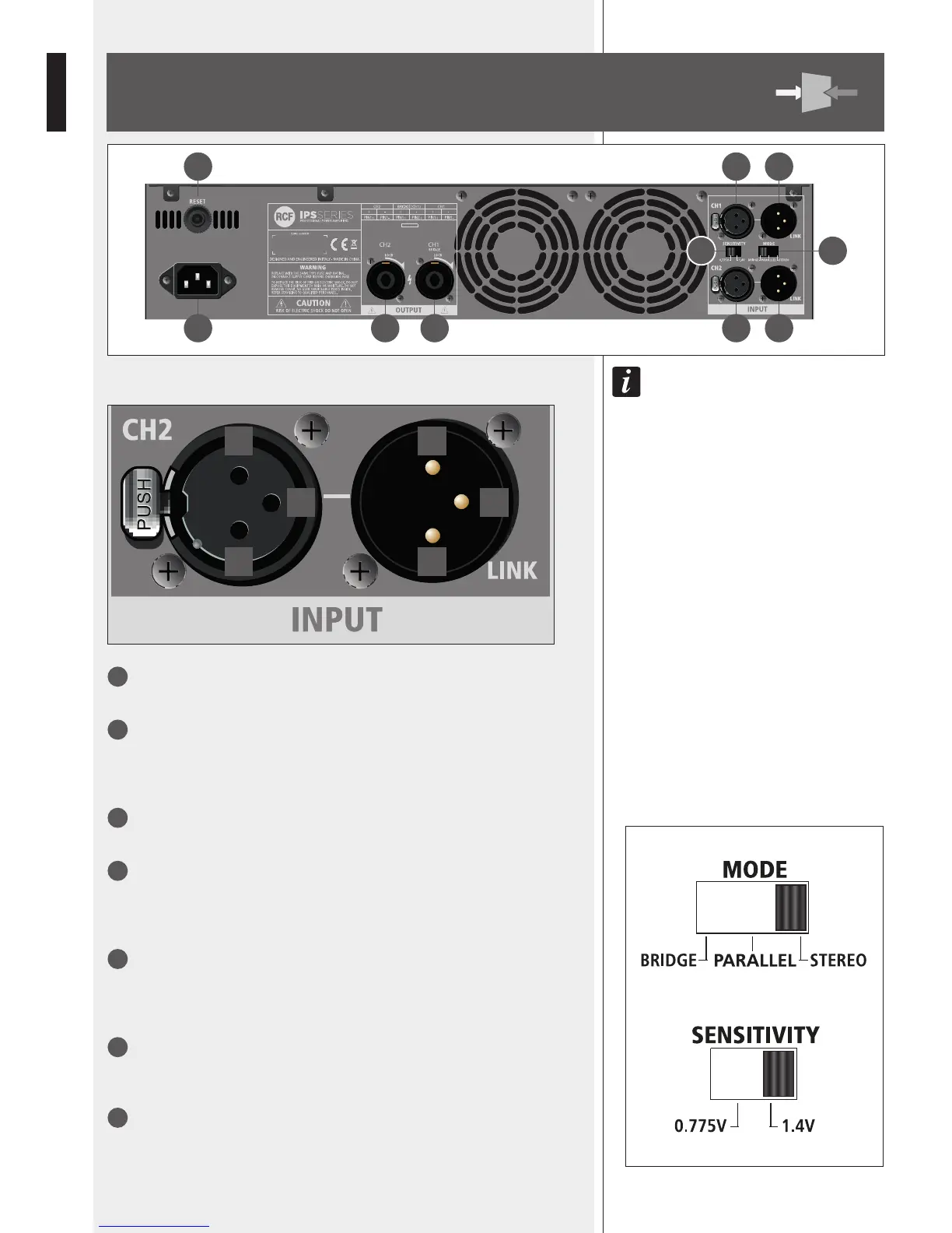
CH1 INPUT
Channel 1 balanced audio input (female XLR connector).
8
CH1 LINK
Channel 1 balanced parallel audio output (male XLR connector).
This output is linked in parallel with the channel 1 input and is useful to link another
amplier.
9
CH2 INPUT (STEREO MODE ONLY)
Channel 2 balanced audio input (female XLR connector).
10
CH2 LINK
Channel 2 balanced parallel audio output (male XLR connector).
This output is linked in parallel with the channel 2 input and is useful to link another
amplier.
11
MODE switch
Before turning the amplier on, set the amplier mode selector to the right position
among BRIDGE, PARALLEL (mono) and STEREO.
See the ‘Operation modes’ manual section.
12
SENSITIVITY switch
Set the sensitivity switch to either 0.775 V or 1.4 V, which is input signal voltage
required to get the maximum power output from the amplier.
13
CH 1 OUTPUT
Channel 1 output to loudspeakers (SPEAKON connector).
If the amplier is set to BRIDGE mode, only connect this output.
See both ‘Operation modes’ and ‘SPEAKON connector wiring’ manual sections.
16 7 8
15 14 13 9 10
1112
1 2
3 3
2 1