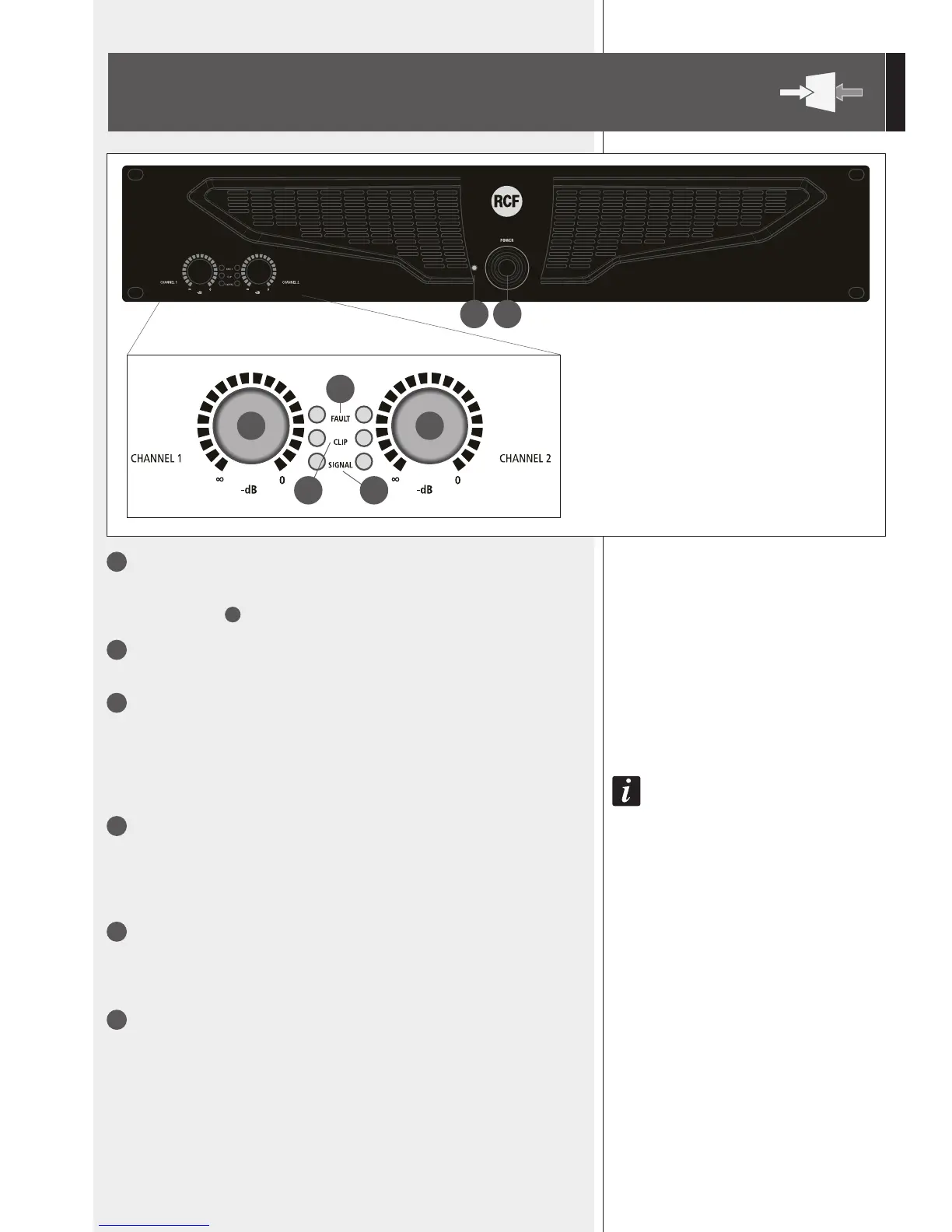
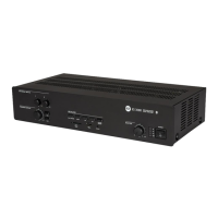
FRONT PANEL
3 3
4
5 6
1
POWER switch
Push to turn on / off the amplier.
Before switching the amplier on, check all cables and turn fully counterclockwise both
channel level controls
3
.
2
POWER LED
When lit, the amplier is switched on.
3
Control (one per channel) to adjust the output level of the respective amplier
channel.
Turn clockwise to increase the output level (0 dB = max. level), turn counterclockwise to
decrease.
4
FAULT LED (one per channel)
When lit, it indicates the internal protection intervention (due to overload, short-circuit,
thermal drift, fault) and the respective channel is muted.
As soon as the problem is solved, this LED will be dark.
When turning the amplier on, this LED stays lit for three seconds.
5
CLIP LED (one per channel)
It blinks when the signal level reaches the clipping point, causing the limiter intervention
of the respective channel.
If it stays lit continuously, the input signal level is excessive.
6
SIGNAL LED (one per channel)
When lit, it indicates the signal presence (above –40 dBu) at the respective input.
12