7
EN
1
PRESET SELECTOR This selector allows to select 3 different presets� By
pressing the selector, the PRESET LEDS will indicate which preset is selected�
LINEAR - this preset is recommended for all regular applications of the
speaker�
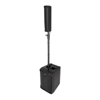
2 SPEAKERS - this preset creates the correct equalization for the use of
two NX 985-A coupled on a subwoofer�
HIGH-PASS - this presets activates a 60Hz high-pass filter for the
correct coupling of the NX 985-A with subwoofers not provided with their
own internal filter�
2
PRESET LEDS These LEDs indicate the selected preset�
3
FEMALE XLR/JACK COMBO INPUT This balanced input accepts a standard
JACK or XLR male connector�
4
MALE XLR SIGNAL OUTPUT This XLR output connector provides a loop
trough for speakers daisy chaining�
5
OVERLOAD/SIGNAL LEDS These LEDs indicate
The SIGNAL LED lights green if there is a signal present on the main
COMBO input�
The OVERLOAD LED indicates an overload on the input signal� It is okay
if the OVERLOAD LED blinks occasionally� If the LED blinks frequently
or lights continuously, turn down the signal level avoiding distorted
sound� Anyway, the amplifier has a built-in limiter circuit to prevent input
clipping or overdriving the transducers�
6
VOLUME CONTROL Adjusts the master volume�
7
POWERCON INPUT SOCKET PowerCON TRUE1 TOP IP-Rated power
connection�
8
POWERCON OUTPUT SOCKET Sends the AC power to another speaker�
Power link: 100-120V~ max 1600W l 200-240V~MAX 3300W
WARNING! CAUTION! Loudspeaker connections should be
only made by qualified and experienced personnel having the technical
know-how or enough specific instructions (to ensure that connections are
made correctly) in order to prevent any electrical danger�
To prevent any risk of electric shock, do not connect loudspeakers when
the amplifier is switched on�
Before turning the system on, check all connections and make sure there
are no accidental short circuits�
The entire sound system shall be designed and installed in compliance
with the current local laws and regulations regarding electrical systems�
3. REAR PANEL FEATURES AND CONTROLS
2
3
4
6
5
7 8
1