DCN: 141-01773-02 1/19/11
31
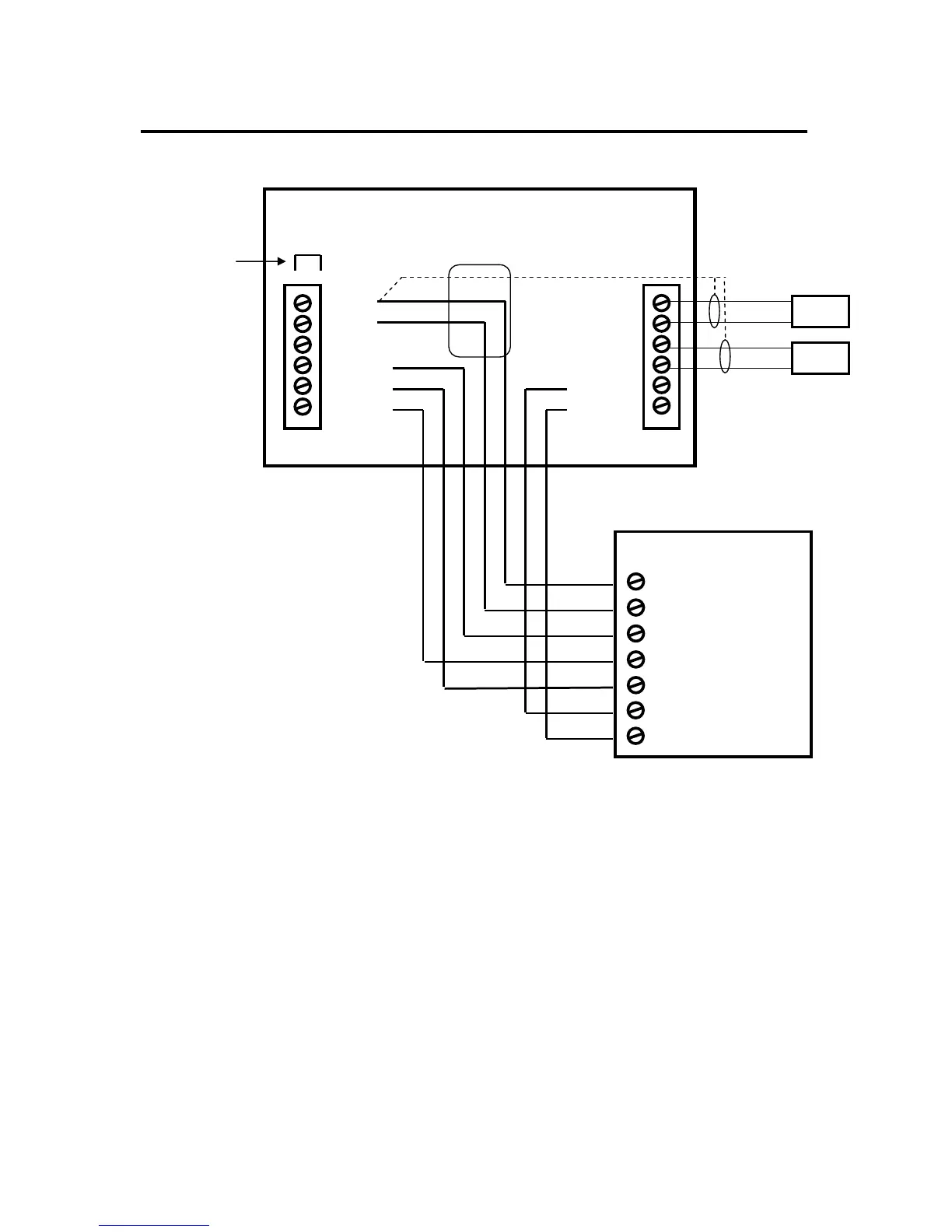
HVAC SYSTEM CONNECTION
Standard Gas/Electric HVAC System Wiring
Installation Notes
Standard HVAC System Setup
You must set up the system configuration in the Installers Settings – Mechanical Settings
Menu (page 23).
System Type: Set the system type to Gas/Elec. This is the default setting.
Fan Type: Set Fan Type to Gas for gas systems or Elec for electric heating systems. Default is Gas
Single Stage systems use W1 for heating stage 1 and Y1 for cooling stage 1.
Two Stage Heating systems use W1 for stage 1 and W2 for stage 2 heating.
(You must enable two stage heating in installer settings)
Two Stage Cooling systems use Y1 for stage 1 and Y2 for stage 2 cooling.
(You must enable two stage cooling in the installer settings)
HVAC system transformer: If you have an integrated heating and cooling system with a single transformer, do NOT cut
jumper JP1. Wire the HVAC system’s 24VAC common (blue wire) to the 24Com terminal and the 24VAC Return (red) wire to
either 24RH or 24RC terminal. This is typical of most central systems.
If you have separate heating and cooling systems with separate transformers, cut jumper JP1. Wire the heating 24V R (red)
wire to the thermostat’s 24RH terminal. Wire the cooling systems 24V R (red) wire to thermostat’s 24RC terminal. Also wire
the cooling systems 24VAC Common (blue wire) to the thermostat’s 24COM terminal.
JP1: internal RC/RH Jumper
on the circuit board.
Cut for separate heating &
cooling transformer systems.
HVAC System
G Fan