Do you have a question about the RDZ RNW 404 and is the answer not in the manual?
This unit is used to control room humidity... Any other different use MUST be agreed...
Installation and maintenance must only be carried out by qualified personnel... must comply with the safety, accident prevention...
The crossed-out rubbish bin symbol... must be collected separately... recover refrigerating gas and lubrication oil...
Upon receipt, check immediately that the packaging is intact... notify the manufacturer of the extent and type of the damage...
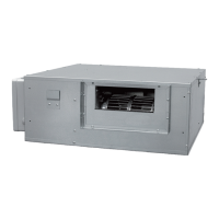
Ductable isothermal dehumidifier designed for horizontal ceiling installation. It consists of...
Table A - Machine Components... Water outlet, Water inlet, Electrical panel, Filter, Fan, Compressor, Exchangers...
RNW 404, Installation / Technical Manual
Mandatory: Condensate drain choosing. Accessories: Hydraulics, Air filters kit.
All the control devices are tested in the factory... Safety check is carried out by the control unit through the values measured by the probes
Compressor, Pre-cooling coil, Evaporating coil, Post-heating coil, Fan, Air filter, Sensors.
Positioning indications: MAX 95% humidity, MAX 30°C temp. Minimum space allowances...
Condensation drain and inlet/outlet pipes must comply with standards. Syphon must be sized...
The dehumidifier must be connected to a disconnected, earthed power socket... electrical system must be protected...
AIR SUPPLY PLENUM. Measures (lxwxh). Collars.
The dehumidifier must be tested together with the panel system... check the water flow rate... check delivery air temperature...
The machine is operational when powered and dehumidification consent is closed. Fan starts first, then compressor...
Legend: L.P., L.G., L.O., L.R. Type of Led Flashing. Signals: Power, Compressor Timing, Water Temp...
Table F - Troubleshooting. Problem/Cause/Remedy. Unit does not start up, Fan starts but compressor does not.
Cleaning the Filter. The dirty filter increases pressure drop... requires periodic cleaning... check every 90 days.
Removing the Fan. Caution! To replace the fan you must remove the lower dehumidifier panel.
Table G - Technical characteristics. Condensation, Rated electrical power, Air flow rate, Refrigerant.
Table H - Acoustic Characteristics. Sound power level [dB] for Dehumidification and Ventilation.
Graphs describe the operating range... SUMMER operation: max water temp 23°C. WINTER mode: 24°C-50°C ventilation.
Table I - Performance in dehumidification mode. Room Temp: 26°C/24°C. Water Temp. vs Litres/Day.
Performance [Pa] vs Air flow rate [m³/h] for different fan speeds.
Head loss [DaPa] vs Water flow rate [l/h].
Schematic showing electrical connections for Compressor, Fan, Power Supply, Sensors, and Consents.
| Brand | RDZ |
|---|---|
| Model | RNW 404 |
| Category | Dehumidifier |
| Language | English |