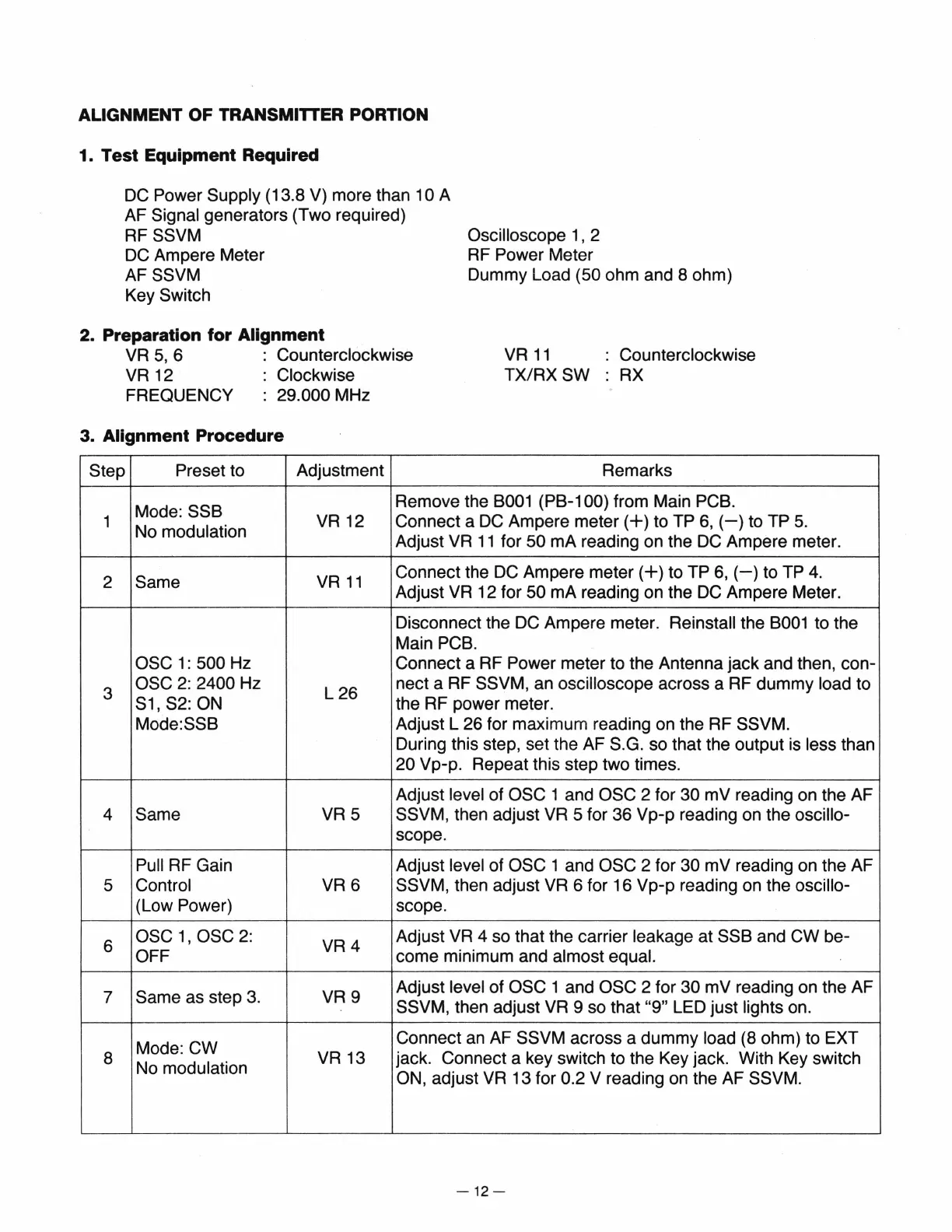
ALIGNMENT OF TRANSMITTER PORTION
1. Test Equipment Required
DC
Power Supply (13.8 V) more than 10 A
AF
Signal generators (Two required)
RF
SSVM
DC
Ampere Meter
AF
SSVM
Key Switch
2. Preparation for Alignment
Oscilloscope 1 , 2
RF
Power Meter
Dummy Load
(50 ohm and 8 ohm)
VR
5,
6 Counterclockwise
VR
11
Counterclockwise
VR
12 Clockwise
TX/RXSW
RX
FREQUENCY :
29.000 MHz
3. Alignment Procedure
Step
Preset to Adjustment Remarks
Mode:
SSB
Remove the
B001
(PB-1 00) from Main PCB.
1
No modulation
VR12
Connect a
DC
Ampere
meter(+)
to TP
6,
(-)to
TP
5.
Adjust
VR
11
for 50 rnA reading on the
DC
Ampere meter.
2
Same
VR
11
Connect the
DC
Ampere
meter(+)
to TP
6,
(-)to
TP
4.
Adjust
VR
12 for 50 rnA reading on the
DC
Ampere Meter.
Disconnect the
DC
Ampere meter. Reinstall the
B001
to the
Main
PCB.
OSC
1:500
Hz Connect a RF Power meter to the Antenna jack and then, con-
3
OSC
2:
2400 Hz
L26
nect a RF SSVM, an oscilloscope across a RF dummy load to
S1, S2: ON
the RF power meter.
Mode:SSB
Adjust L 26 for maximum reading on the RF SSVM.
During this step, set the AF S.G. so that the output
is
less than
20 Vp-p. Repeat this step two times.
Adjust level of
OSC 1 and OSC 2 for 30 mV reading on the AF
4
Same
VR5
SSVM, then adjust
VR
5 for 36 Vp-p reading on the oscillo-
scope.
Pull RF Gain Adjust level of OSC 1 and OSC 2 for 30 mV reading on the AF
5 Control
VR6
SSVM, then adjust
VR
6 for 16 Vp-p reading
on
the oscillo-
(Low Power)
scope.
6
osc
1,
osc
2:
VR4
Adjust
VR
4 so that the carrier leakage at SSB and CW be-
OFF come minimum and almost equal.
7 Same as step
3.
VR9
Adjust level of OSC 1 and OSC 2 for 30 mV reading on the AF
SSVM, then adjust
VR
9 so that "9" LED just lights on.
Mode:
CW
Connect
an
AF SSVM across a dummy load (8 ohm) to EXT
8
No modulation
VR13
jack. Connect a key switch to the Key jack. With Key switch
ON, adjust
VR
13 for 0.2 V reading on the AF SSVM.
-12-