APPENDIX
for
VHF
-MlD
Band tor European/Australian models
veo
ALIGNEN T
Step 1: Conneet a DC VTVM to TP·l 04 and groun d
Step 2: Progr
amC
H1, 2 and 3 as fo liows:
CHl (68
MHz), CH2 (78 MHz), CH3 (88 MHz)
Step 3: Select channel 3 (88 MHz) and adjust TC·10l for 9.0V on th e DC VTVM
Step 4 : Select chan nel 1 (68 MHz) and adjust T l03 for 1.OVon the DC VTVM
Step 5: Repeat step
s3an
d4un
til no improvement is observed.
The DC VTVM should show as below .
68 MHz Voltage of TP
·l04
1.0V
78 MHz Voltage of TP
·l04
3.4V :!:0.3V
88 MHz Voltage of TP·104 9.0V
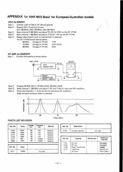
RF AMP ALlGNMENT
Step 1: Connect instruments as shown below.
Step 2: Program 68 MHz (C
Hl),
78 MHz (CH2l. 88 MHz (CH3 1.
Step 3: Select Channel 1 (68 MHz) and adjust T10 l and
Tl02
for maximum RF waveform.
Step 4: Check the Channe ls 1 - 3 one by one for max imurn RF waveform.
Slight d eviation as shown belo
wist
oierabie.
~
0
rl--
-
--t-1
c-t-- -------I
Tr
- - -
-."..-:-.--
- - -
PARTS LIST REVISION
Rel . No.
ValuIt
IVoltage
Toleran ee
Mate rial
(VI
(\!bI
Cl 02
33 pF
I
50 . 10
Ceramic
Cl 0S
33p F
50
.1 0
Caramie
C114
47pF
50
. 10
Ceram ic
C116
33pF
50
. 10
Ceram ie
C
l17
5pF
50
. 0.5p F
Ceram ic
C250
10pF
50
' 0. 5pF Ceramic
~-
~
~
~
============
Ref. No .
Type No. RSPa
rtNo
.
Subst itute
Typ e No.
T101
RF Cail
GR·N553
Tl02
RFC
a il
GR·N553
Tl 0S
Powe r T ransformer
K686 2
a .T.F
Trap Filter 20LTR-141
AC Card HAR Class2