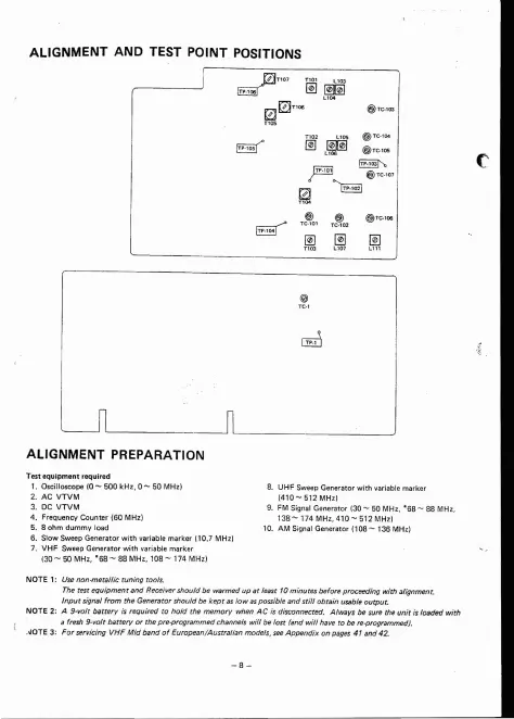
ALlGNMENT AND TEST
POINT
POSITIONS
j
~T10
7
@j~
@~
,.
I
TP-106
WJ0
T1rAö
g"
&1
2
L
~
@"
'·
I
@JT C-l05
~
~
I@ TC-l 07
~
~
~
T~O
'
T
~02
@) TC-lrAö
~
~
~
T!
'
~
ALlGNMENT PREPARATION
Testequ
ipmentrequired
1. Oscilloscope (0 - 500 kHz, 0 - 50 MHz )
2. AC
VTVM
3. DC VTVM
4. FrequencyCounter (SOMHz)
5.8ohmdummyload
S. Slow Sweep Generator with variabie marker 110.7 MHz)
7. VHF Sweep Generator with variabie marker
(30 - 50 MHz, * 6
8-
88 MHz , 108
-17
4 MHz)
8. UHF Sweep Generator with variabie marker
(41
0-
512 MHzl
9. FM SignaI Generator (30
- 50 MHz, *S8 - 88 MH z,
138
-1
74 MHz, 410 - 512 MHz)
10. AM Signal Generator (108
- 136 MHz)
NOTE1
: Use non -mets ttic tuning tools.
The test eauloment and Receiver should be warmed up at least 10 minutes befo re proceeding with alignment.
Input signal from the Generator should be kept as low as possible and still obtain usabie output.
NOTE 2: A 9·volt betterv is required to hold the memory when AC is disconnected . Always be sure the unit is loaded with
a fresh 9·volt betterv or the pre-programmed channels will be last rand will have to be re-proçremmed}.
.•OTE 3: For servicing VHF Mid band of European/Australian models, see Appendix on pages 4 1and 42.