UHF BAND
Step 1: Connect a DC VTVM to TP-104 and ground .
Step 2: Program
CH1,2and3
asfollows
:
Chl (410 MHz), CH2 (430 MHz), CH3 (512 MHz!.
Step 3: Select Channel 3 (512 MHz) and adjust TC·106 for 9
.0Von
the DC VTVM.
Step 4: Select Channel 1 (410 MHz) and adjust L111 for 1.OVon the DC VTVM.
Step 5: Repeat steps 3 and 4 unt il no improvement is observed.
The DC VTVM should show as below.
410 MHz Voltage at
TP·l04
1.0V
430 MHz Voltage at TP·104
1.8±
0.3V
512 MHz Voltage at TP·104 9.0V
RF AMP ALlGNMENT
VHF LO BAND
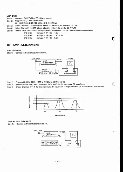
Step 1:
Connectinstrumentsasshownbelow.
Step 2: Program 30 MHz (CH1). 40 MHz (CH2) and 50 MHz (CH31.
Step 3: Select Channel 2 140 MHz) and adjust
nOl
and
Tl02
for maximum RF waveform . { .
Step 4: Check Channels 1
- 3 for the maximum RF waveform. A slight deviation (as shown below) is acceptab le.
/\\71\
I ,
VHF Hl AND
AIRCRAFT
Step 1: Connect instruments as shown below .