OVERALL ALlGNMENT AND SENSITIVITY MEASUREMENT
Step 1: Con neet Signal Gene
rator
(SSG) to
ANTenna
jack and AC VTVM to EXT. SPKR Jack .
Step 2: Turn SOUELCH fully counterclockwise. Set for recept ion of the channels noted in the following chart.
SettheSSG
tothe
center
ofeach
band.
CH
BAND FREO .
1 VHF LO (MlD) 40 MHz (78 MHz)
2
VHF Hl
160MHz
3 UHF
512MHz
4
AIRCRAFT
120MHz
Step 3: Set the Signal
Generato
r
frequency
to 512 MHz (channel 3). Readjust TC
-l07
for maximum sensitivitv,
Step 4: Set the Signal
Generator
frequency to 120 MHz
(channeI41.
Adjust
Tl04,
Tl06
and
Tl07
for
maximum
sensitivity.
Step 5: For each f
requenc
y
/channel,
set Signa I
Generator
to each frequency (FM: 3 kHz deviation, AM: 60% rnodu-
lation) . Set VOLUME
control
for 0 dB (0.775 V) reading on the VTVM.
Step 6: Turn off the
modulation
and measure the (S + Nl/N ratio.
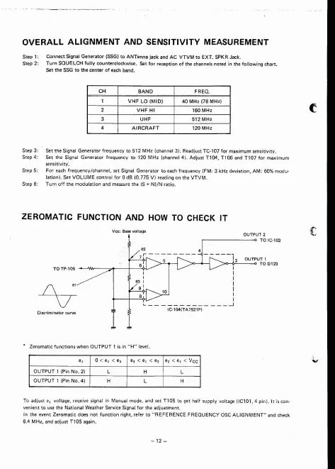
ZEROMATIC FUNCTION AND HOW Ta CHECK IT
I
* Z
eromatic
functions
when
OUTPUT
1 is in
"H"
level.
To
adjust
el voltage, receive signal in Manual mode , and set T105 to get half supply voltage (IC101, 4 pin). It is con -
venienttousethe
National
WeatherServ
iceSignalfortheadjua
tment
.
In the event
Zeromatic
does not
function
right, refer to " REFERENCE FREQUENCY asc
ALlGNMENT"
and check
6.4 MHz, and adju
stT105aga
in.