Reclaim Energy | Owners/Installation Manual – Controller v1.1
6
3
Mounting Follow these steps:
1. Allow for the enclosure dropping 5mm (1/5 inch) from screw
centres once mounted (keyhole mounting).
2. Place the printed drill guide template (that ships with the
controller) against the wall, checking for level alignment. All
four mounting holes should be used with at least two fi rmly
secured into wood or masonry.
3. Mark and drill/screw as appropriate leaving the heads of the
screws above the surface by approximately 3mm (1/8 inch).
4. Place the unit over the four screw heads. The unit should
slide down 5mm into the ‘key’ slots and become secured to
the wall. You might need to adjust the screw height to obtain
a secure fi t.
Sensor Mounting WARNING: It is CRITICAL the sensor is mounted correctly for
accurate readings, safe and effi cient operation of the system,
durability of the sensors
The sensor should be fi tted into a dry metal immersion ‘pocket’
in the hot water cylinder. Apply plenty of heat transfer
compound (available from your distributor) between the sensor
and the lining of the ‘pocket’ then seal against water ingress
where the cable exists the cylinder with neutral cure silicon.
Connect to Heat Pump Plug RJ45 cable into the heat pump.
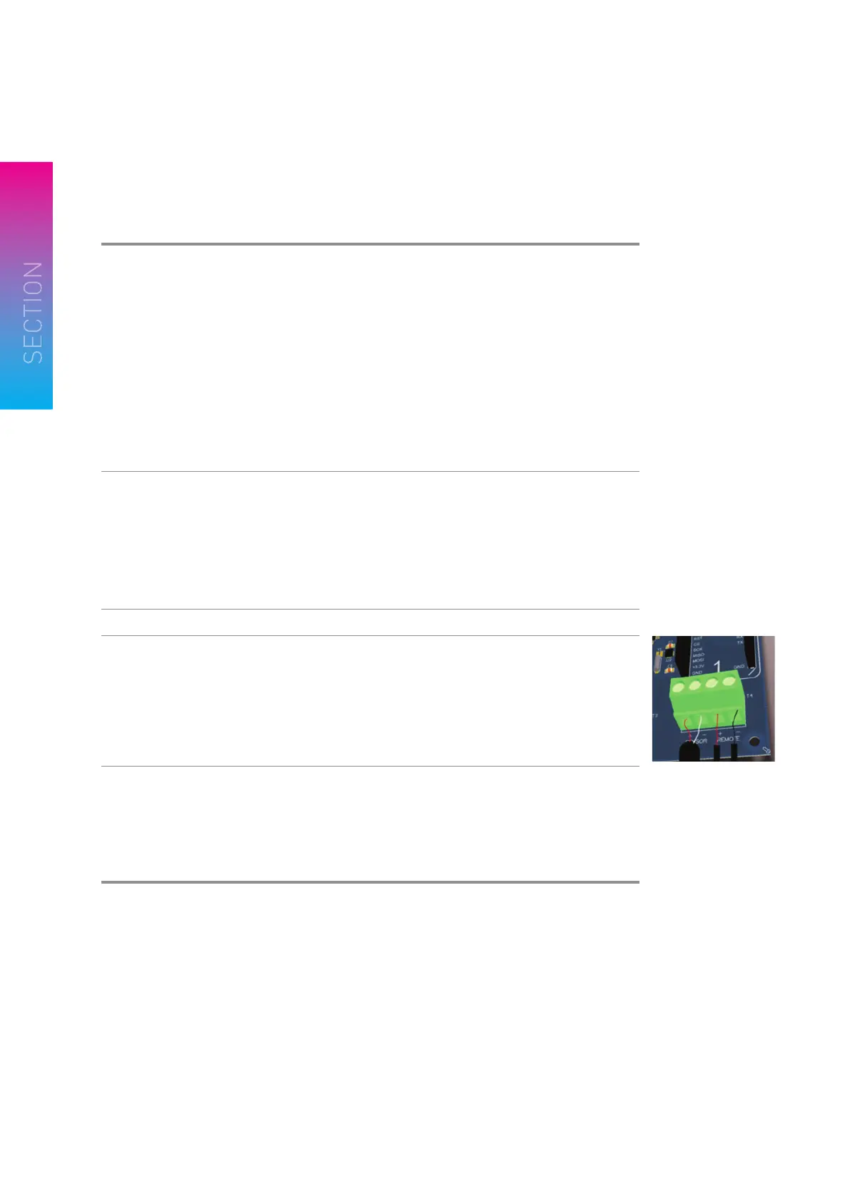
Connect PV Remote
wires (only if applicable)
A ‘clean set of contacts’ (passive only) is expected for this input.
If not, then the controller could be damaged.
The remote input is accessible by removing the cover.
Ensure mains power is isolated during this work.
Loosen the cable gland and thread the cable next to the
sensor cable.
Wire in as indicated on diagram on the right.
Plug in the controller
to the power source
Before power up read all safety instructions, warnings and
liability statements.
Controller will run through start up checks including lighting
all LEDs. Then fi rst display will be the time of day the controller
thinks it is. Page 7 has details on how to adjust the time.
INSTALLING THE RECLAIM CONTROLLER
SENSOR REMOTE

 Loading...