Documentation RM-BV4 Micro DP
RDN 10000662 6 24.01.2014
The potential-free "Alarm" relay output, terminals 4 (NO), 5 (COM) and 6 (NC) is used for self-
monitoring of the RM-BV 4 Micro DP. This output is energised during trouble-free operation.
Following events will cause the relay contact to drop off:
Failure of the supply voltage
Broken wire on one of the connected valves
The differential pressure has fallen below the set ∆p-Min switch point (parameter 09).
The differential pressure has exceeded the set value ∆p Max. alarm sw
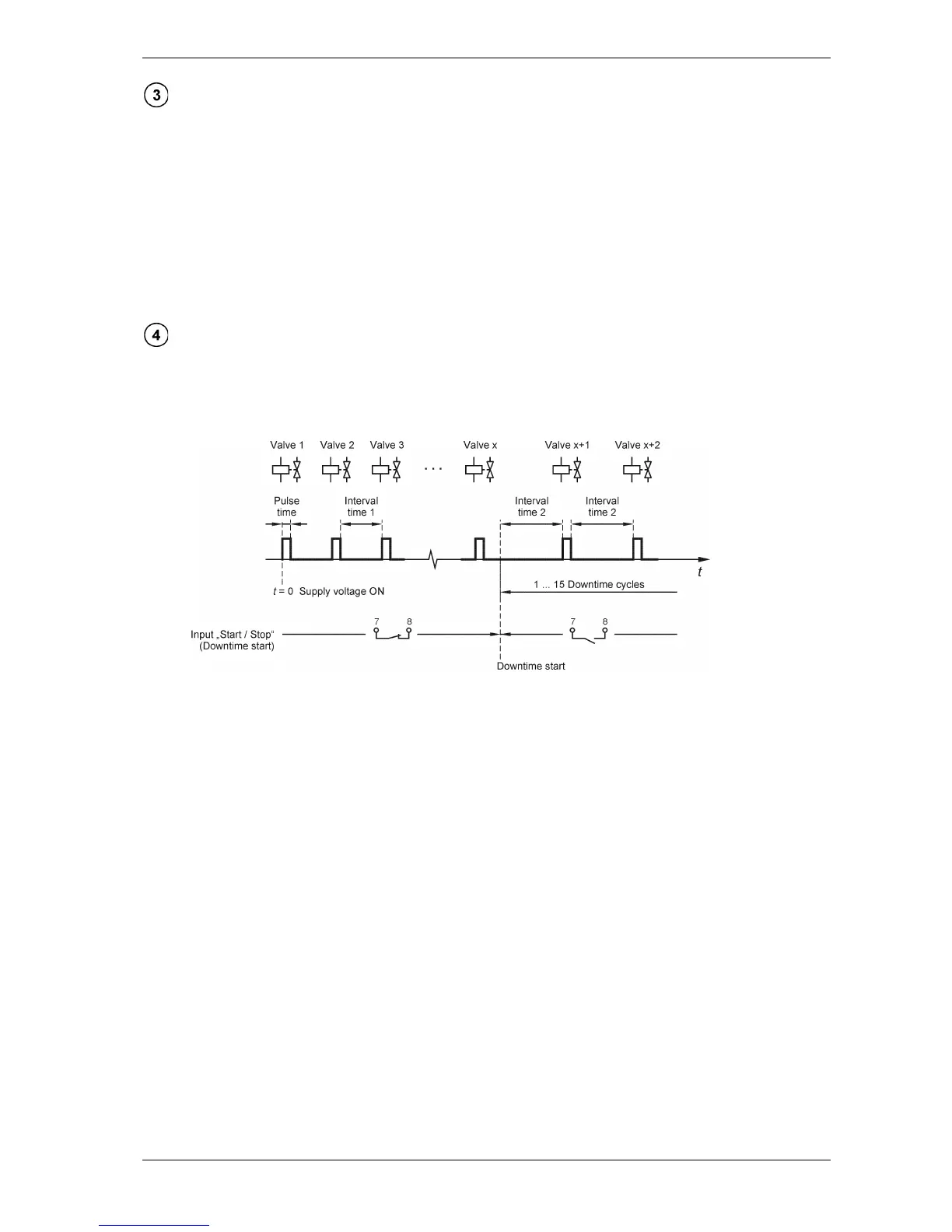
The input „Start / Stop“ for downtime cleaning (terminals 7, 8) is factory-bridged.
When a contact
(NC) connected to this input is opened, the set downtime cycles are started, beginning with the
interval time 2. Downtime cleaning is resumed with the valve following to the last controlled valve.