33
11. Maintenance - cont.
the back of the headstock. Do not over tighten
this, the bolt should only be turned until finger
tight Fig. 11.23, then apply a 1/4 of a turn with
an Allen key Fig. 11.24.
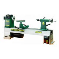
22. The belt should now be placed on the
pulley and inner locking ring tightened. Once
the locking ring is tightened by hand use the
notches to lever the ring round and fully tighten
it. Fig. 11.25. This will pull the bronze bearing
in place on the spindle.
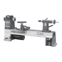
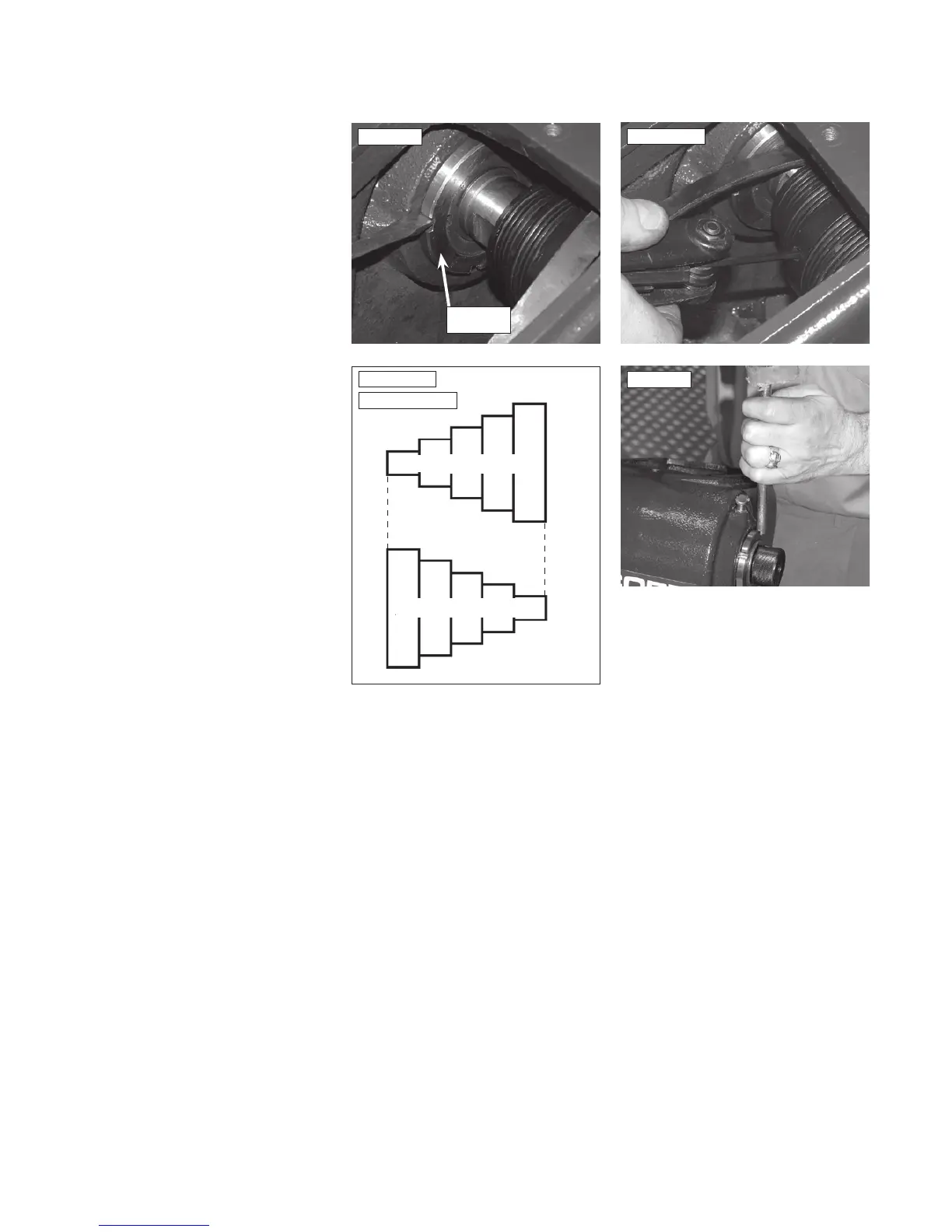
23. Position the spindle pulley so as to line up
with the motor pulley Fig. 11.26. Tighten the
spindle pulley bottom grub screw ensuring that
it locates on the spindle flat, then replace the
locking grub screw. Fig. 11.27.
24. Finally tighten the outer locking ring, by
placing the brass drift in one of the notches
and tapping it with a mallet Fig. 11.28. The
procedure is now complete.
25. Re-tension belt by applying slight downward
pressure on motor then tighten the tension lever.
With the belt in position and the headstock
cover replaced the machine should be run for a
little time to enable the belt to bed in.
Note: The bearing may need to be adjusted -
see section 10.
Note: If a new bearing has been fitted this will
need running in - see section 7.
Check final adjustment of the bronze bearing
(after running it in if new) and adjust as
necessary following instructions in section 10.
Fig.11.25
Fig.11.27
Fig.11.28
Inner locking
ring
Motor Pulley
Spindle Pulley
Fig.11.26
Pulleys aligned
 Loading...