22
12. Maintenance
To remove the belt from the spindle pulley the spindle must be detached
from the headstock.
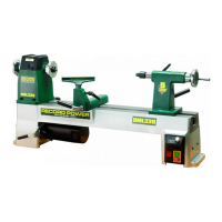
The spindle assembly is shown in Fig 12.6.
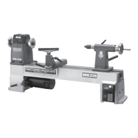
Remove the circlip shown in Fig 12.7 from the outside of the headstock
using
circlip pliers.
Remove the two blind set screws of the sensor plate using a 3 mm hex
wrench as shown in Fig 12.8.
The spindle pulley features 4 blind set screws as shown in Fig 12.9. In each
position there are 2 screws. Remove all 4 screws from the pulley.
The sensor plate and pulley are now loose on the spindle, reducing risk of
damage when the spindle is removed.
Remove the hand wheel by unscrewing it clockwise.
NOTE: The hand wheel features a left-hand thread.
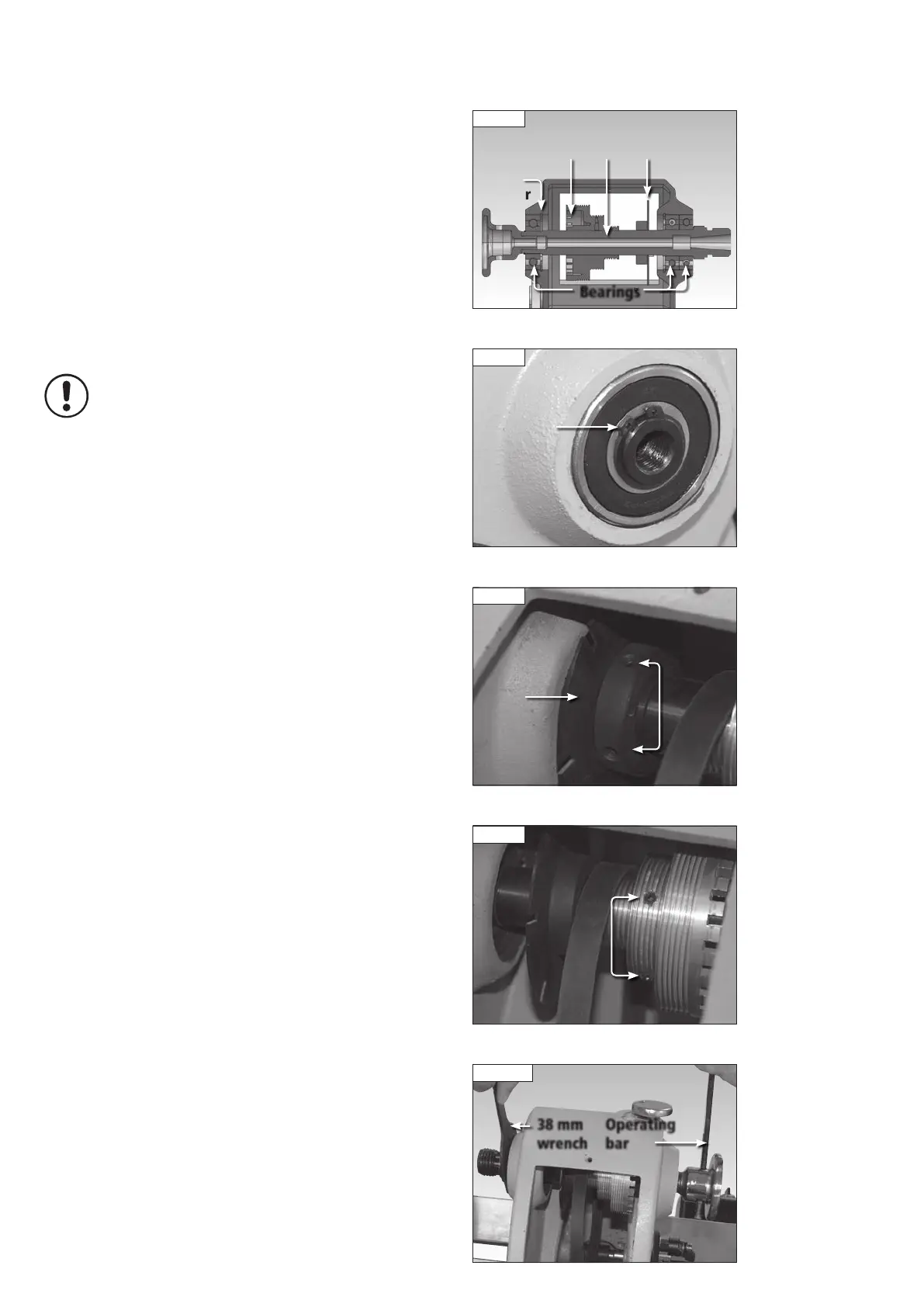
It may be necessary to hold the spindle in place using the 38 mm wrench as
shown in Fig 12.10 and use the operating bar fitted to the hand wheel.
Use a soft-headed mallet to carefully knock the spindle from the headstock
housing.
Remove the bearings from the spindle using a bearing press.
Remove the bearing from the head stock (located on the same side as the
hand wheel) and replace.
Reassemble the spindle assembly, ensuring the sensor place passes freely
through the sensor.
Fig 12.7
Circlip
Fig 12.6
Wave
washer
Bearings
SpindlePulley Sensor plate
Fig 12.10
38 mm
wrench
Operating
bar
Fig 12.8
Blind set
screws
Sensor
plate
Fig 12.9
Blind set
screws
 Loading...