11
8. Assembly - cont.
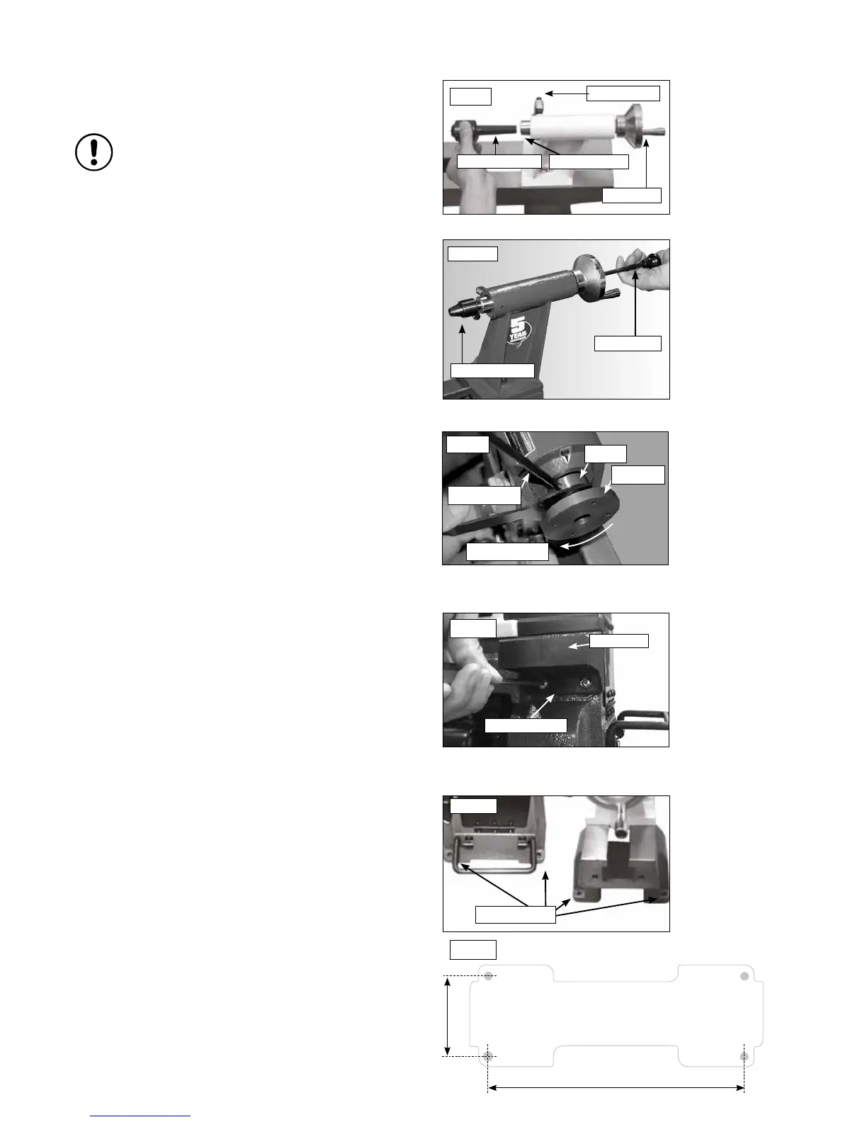
Pan head screw
Tool holder
Fig.8.13
Fig.8.14
Mounting holes
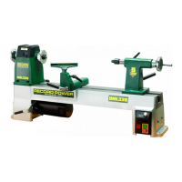
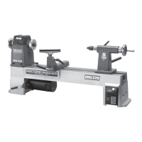
Secure Lathe to a Solid Work Surface
The lathe must be attached to a solid work surface or stand, not less than 25
mm thick. Four mounting holes are easily accessible at the base of the lathe,
Fig.8.14. Drill holes in the work surface, using a 13 mm or 1/2” drill bit,
following the measurements shown in Fig. 8.15.
Note: Use of the DML305/A Leg Stand is recommended.
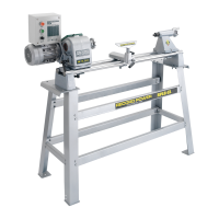
To remove the revolving centre from the tailstock spindle insert the knockout
bar into the hole in the centre of the tailstock hand wheel and give the revolving
centre a sharp knock to dislodge it from the tailstock, see Fig 8.11.
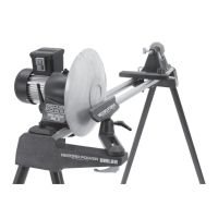
Fitting the Faceplate to the Headstock
Thread the faceplate clockwise on to the headstock spindle. Place the
knockout bar in the circular hole in the spindle nose and hold firmly to
ensure the spindle does not turn. Now use the spindle wrench on the
faceplate collar to tighten the faceplate, turning clockwise, see Fig 8.12.
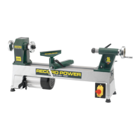
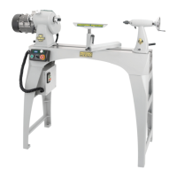
Fitting the Revolving Centre to the Tailstock
First ensure the locking handle is loosened then insert the revolving centre
into the tailstock spindle and tighten the locking handle, Fig.8.10.
Please note: Before inserting tapered attachments into the
headstock or tailstock spindle, always ensure that the taper
is clean and free of any waste material that may cause
misalignment or vibration. Always fully seat the taper by
tapping it into place with a wooden mallet.