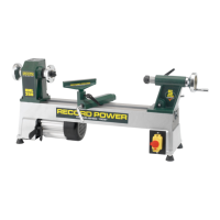
1 Motor
2 Lifting handle
3 Switch
4 Hand wheel
5 Indexing assembly
6 4 prong drive centre
7 Faceplate
8 Tool rest
9 Tool rest holder
10 Revolving centre
11 Tailstock
12 Tailstock hand wheel
13 Lathe bed
14 Tool rest holder locking lever
15 Tailstock spindle locking lever
16 Tool holder
17 Tailstock locking lever
9
15 16
2
3
5
4 4
8 10 11 126
17
7
13141
The machine must be unplugged and the power switch must be
in the OFF position until the machine is completely assembled.
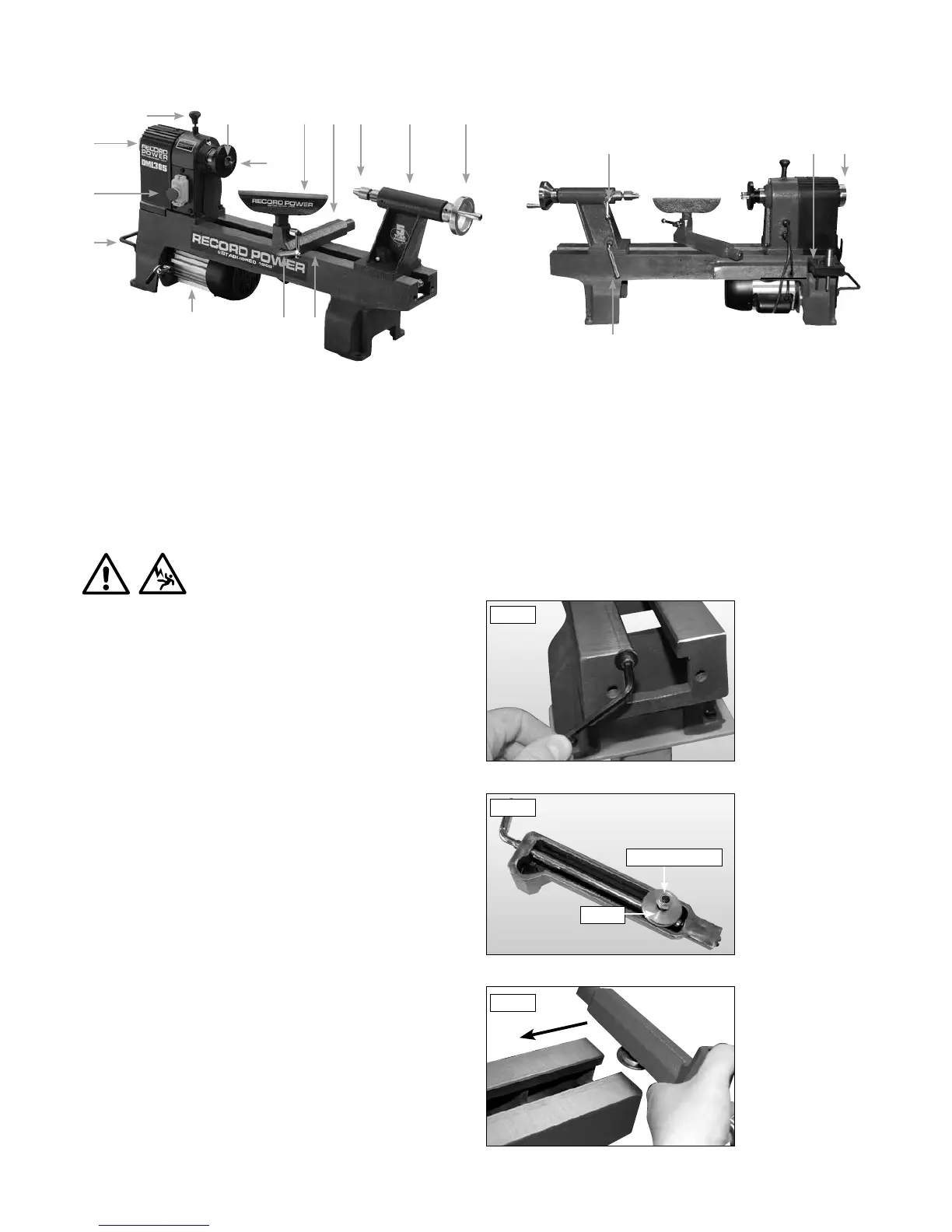
Installing the Tool Rest Holder to the Lathe Bed
To allow the tool rest holder to be attached to the lathe, the tailstock must
first be removed. Remove the hex head screw and retaining washer at the
end of the lathe bed to allow the tailstock to be slid from the lathe bed,
Fig 8.1.
On the underside of the tool rest holder is a bolt with a nylon locking nut
which holds the clamp in place, Fig 8.2. Loosen the nylon locking nut until
the tool rest holder can be slid onto the lathe bed, Fig 8.3.
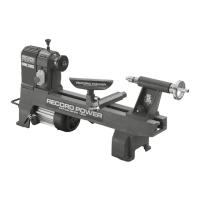
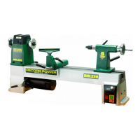
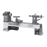
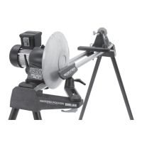
7. Getting to Know Your Lathe
8. Assembly