18
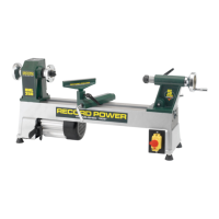
With the headstock cover open, loosen the locking arm. Raise the tension
lever to release tension on the motor pulley and tighten the locking arm, see
Fig. 11.7. Check speed and belt position chart inside access the cover to
determine the spindle speed required.
Move the drive belt to the desired pulley combination. Loosen the locking
arm and lower the tension lever. In addition to the weight of the motor, a
little further pressure may need to be applied to correctly tension the drive
belt. Tighten the locking arm and close the headstock cover.
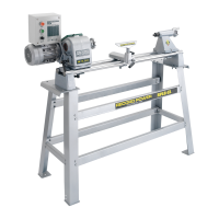
Indexing Lock
The indexing lock is positioned on the top of the headstock. The headstock
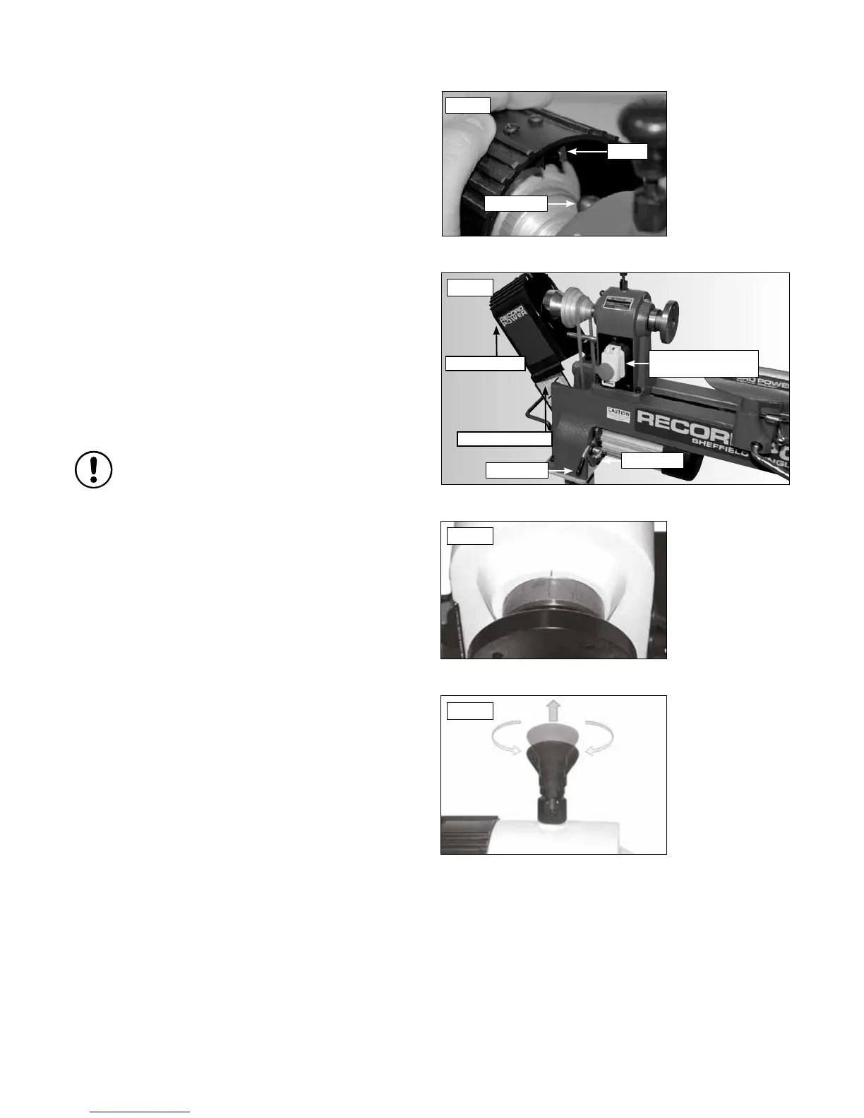
indexing feature has 12 equally spaced positions, see Fig. 11.8. The spring
loaded locking pin assembly is engaged by turning the knob a half turn
allowing it to drop into the desired position. To disengage, lift the lock knob
up and turn a half turn either direction, see Fig.11.9.
The 12 position indexing feature allows accurate pattern work on projects
such as straight fluting, grooving, drilling, lay out and more.
To use the indexing feature, disengage the locking knob by lifting up and
rotating half a turn. Move the spindle to the desired position and engage the
locking knob to hold the spindle in position.
Please note: The indexing mechanism should not be used as
a method of holding the spindle whilst removing accessories
such as face plates, chucks etc. Always hold the spindle with the
knockout bar in the hole on the spindle nose when
removing accessories.
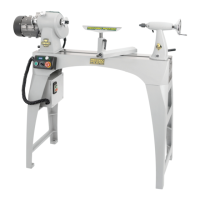
Starting & Stopping the Lathe
To turn the lathe on, press the green switch marked ‘I’ on the headstock,
located beneath the red emergency stop button.
To stop the machine, press the red button marked ‘O’ on the headstock,
located beneath the red emergency stop button.
To stop the machine in an emergency, press the large red button located on
the headstock, Fig 11.7.
In the Event of a Blockage or if the Machine Stalls
If the lathe stalls due to a dig in, simply removing the turning tool from the
work piece will normally allow the work piece to start turning again.
In the event of a blockage (for example, if the work piece becomes trapped
against a fixed part of the machine) switch off the machine immediately, by
pressing the red button marked ‘O’ on the switch.
Locate and rectify the source of the blockage and ensure that the work piece
can be rotated freely by hand before attempting to re-start the machine.
To re-start the machine, press the green button marked ‘I’ on the switch.
In the Event of a Power Failure
The lathe is fitted with a no volt release (NVR) switch to protect the user
against automatic starting of the machine when power is restored after a
power failure.
In the event of a power failure, first locate and rectify the source of the
failure. If the fault is within the power circuit of the workshop, there may be
an underlying cause (circuit overload etc.) that should be investigated by a
qualified electrician, before attempting to restore the power source.
Once the power is restored, the machine can be re-started by pressing the
green button marked ‘I’ on the switch.
11. Adjustments and Operations - Cont.
Fig.11.9
Fig.11.8