SERIES 2000 PAGE 4.
INSTALLATION INSTRUCTIONS
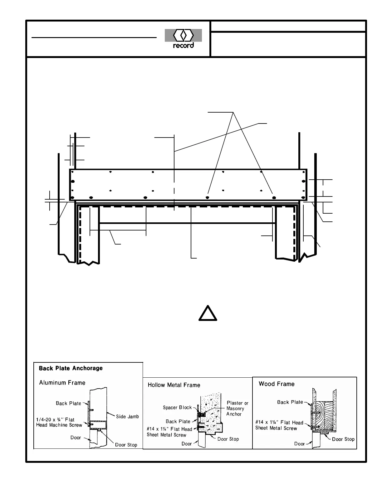
BACK PLATE INSTALLATION
HOLE PREPARATION INSTRUCTIONS
For Metal frames with 1/8” or greater material thickness,
drill #7 hole and tap for 1/4-20 x 3/4” machine screws as
required. For Metal frames with less than 1/8” material
thickness or Wood frames, drill 3/16” pilot hole for #14 x
1 1/4” sheet metal screws as required.
Note:
When door stop is more
than 1/2” high, the back
plate should be lowered
by the amount exceed-
ing 1/2” for Regular.
1”
Top of
Door
14 3/8” (Ref. only)
1/2”
*1 3/8”
*1/2”
Centerline of
Operator Pinion
3”
*Plate Location Dimensions
8” on centers
across as
required
2 3/8”
Top
Of
Door
Note:
LH Regular or RH Parallel shown
RH Regular or LH Parallel Opposite
Slide Arm same as Parallel Arm
All door frames for regular arm and parallel
arm operation must be provided with door
stops.
Doors and frames for parallel operation with
panic breakaway must be center pivoted or
be capable of swinging in both directions
with no stops.
!
KEANE MONROE
a member of the record group
MONROE, NC, USA 28111 800 438 1937