SERIES 2000 PAGE 3.
INSTALLATION INSTRUCTIONS
ELECTRICAL PREPARATION (cont.)
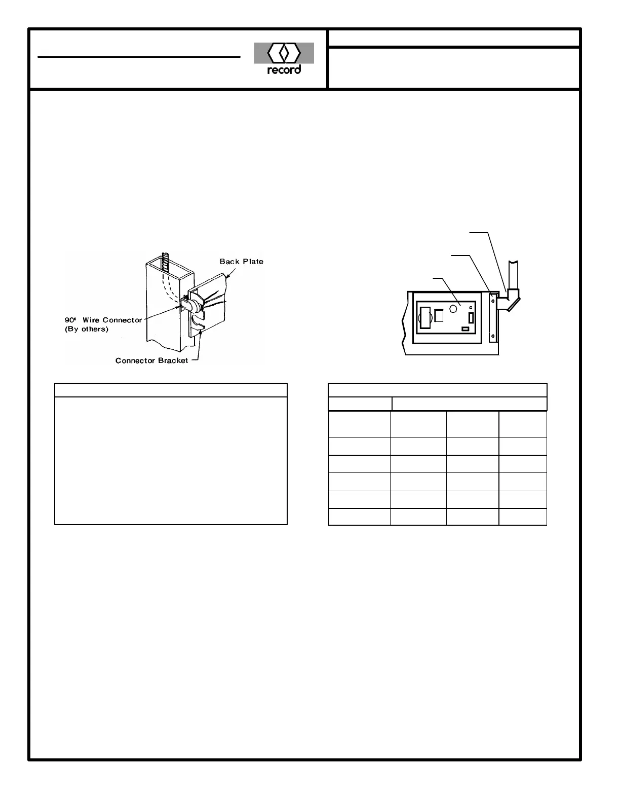
CONCEALED
Run flexible conduit or 3-wire cable down
side jamb, through cut-out. Trim sufficient
length of wire and insert into 90 degree con-
nector. Attach connector to bracket and se-
cure with lock nut. Trim wire to proper
length when wiring unit. Secure ground wire
to operator base or control.
ELECTRICAL POWER
SURFACE MOUNT
Connect 90 degree elbow to bracket as
shown, pull sufficient length of wire. Trim
to proper length when wiring unit. Se-
cure ground wire to base or control.
Control
Conduit Bracket
90° Elbow
ELECTRICAL POWER SUPPLY
1. Single Operator (1 Motor)
115-120 Volt, 60 Hertz, 15 Amp.
2. Dual or Pair of Single Operators (2 Motors)
115-120 Volt, 60 Hertz, 20 Amp
3. Pair Dual or Four Single Operators (4 Motors)
115-120 Volt, 60 Hertz, 30 Amp.
Note: All 3-wire Systems (2 wire w/ground).
All fuses & circuit breakers to be Slow Blow Type.
RECOMMENDED WIRE SIZE CHART
Length of Run Wire Size
Distance to
Main Panel
Single Oper.
(1 Motor)
Dual Oper.
(2 Motors)
Pair Duals
(4 Motors)
100' #14 #12 #10
200' #12 #10 #8
300' #12 #8 #6
400' #10 #8 #6
500' #10 #8 #6
BACK PLATE INSTALLATION
Before preparing jamb for back plate, determine the hand of the door. If door hand is LH Regular
or RH Parallel proceed as shown on next page. If the door hand is RH Regular or LH Parallel, re-
verse the back plate end to end so that it is opposite as shown. See Page 1 for Hand of Door
Identification.
MOUNTING BACK PLATE
Mount to prepared jamb using furnished flat head screws suitable for prepared holes.
Note: For swing clear hinges, place end of back plate 1 3/8” beyond the centerline of hinge pin or
order special length back plate and cover (See Installation of Cover and Back Plate of a different
length than door opening).
KEANE MONROE
a member of the record group
MONROE, NC, USA 28111 800 438 1937