9
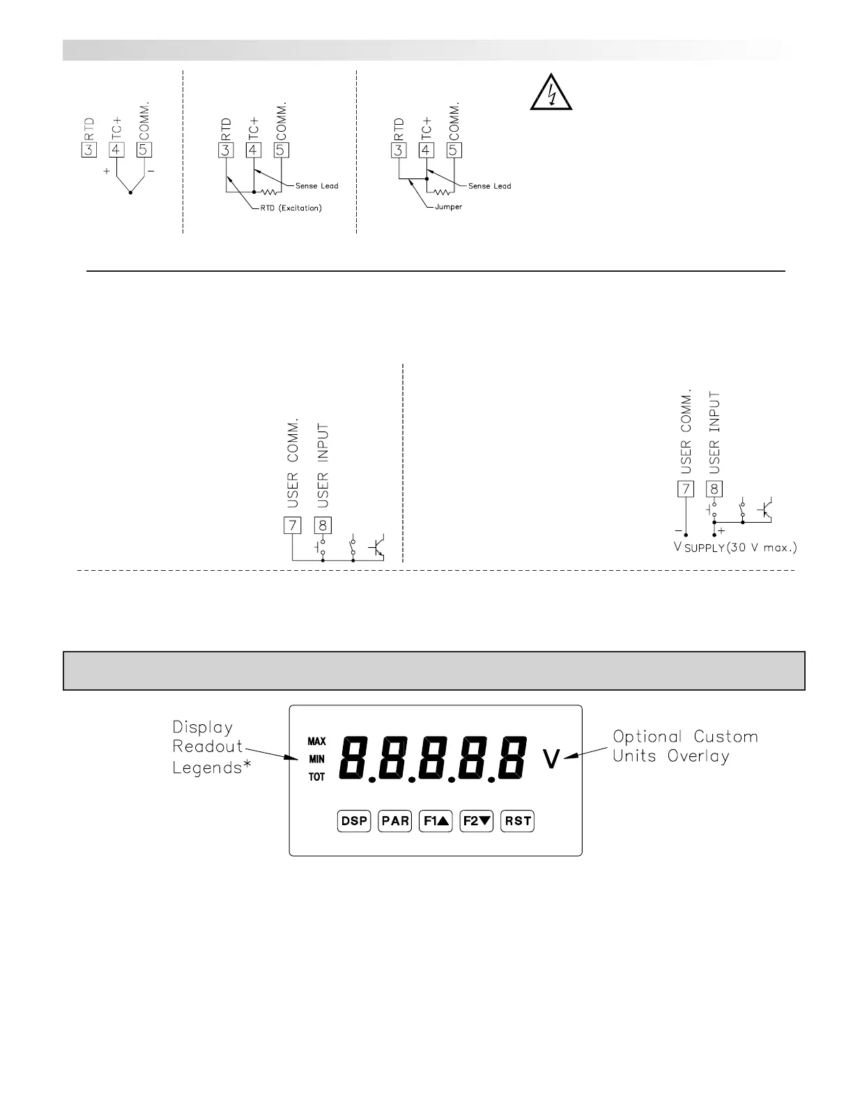
DP5T INPUT SIGNAL WIRING
3-Wire RTD
Thermocouple
2-Wire RTD
CAUTION: Sensor input common is NOT isolated
from user input common. In order to preserve the
safety of the meter application, the sensor input
common must be suitably isolated from hazardous
live earth referenced voltages; or input common
must be at protective earth ground potential. If
not, hazardous live voltage may be present at the
User Input and User Input Common terminals.
Appropriate considerations must then be given to
the potential of the user input common with
respect to earth common.
Sinking Logic
Terminal 8:
Terminal 7: }
In this logic, the user input of the meter
is internally pulled up to +5 V with 22 K
resistance. The input is active when it is
pulled low (<0 .9 V).
3.3 USER INPUT WIRING
Before connecting the wires, the User Input Logic Jumper should be verified for proper position. If not using the User Input then skip this section.
Connect external switching device between the
User Input terminal and User Comm.
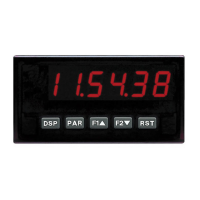
* Display Readout Legends may be locked out in Factory Settings.
** Factory setting for the F1, F2, and RST keys is NO mode.
RST
F2
W
F1
V
PAR
DSP
KEY
Hold with F1V, F2
W
to scroll value by x1000
Reset (Function key)**
Decrement selected parameter value
Function key 2; hold for 3 seconds for Second Function 2**
Increment selected parameter value
Function key 1; hold for 3 seconds for Second Function 1**
Store selected parameter and index to next parameterAccess parameter list
Quit programming and return to display modeIndex display through max/min/total/input readouts
PROGRAMMING MODE OPERATIONDISPLAY MODE OPERATION
4.0 REVIEWING THE FRONT BUTTONS AND DISPLAY
Sourcing Logic
Terminal 8: + VDC thru external switching device
Terminal 7: -VDC thru external switching device
In this logic, the user input of the meter is
internally pulled down to 0 V with 22 K
resistance. The input is active when a voltage
greater than 3.6 VDC is applied.