3
1. SENSOR INPUT:
Sample Period: 100 msec (10Hz rate)
Step Response Time: 300 msec typical, 400 msec max to
within 99% of final value with step input.
Failed Sensor Response:
Main Control Output(s): Programmable preset output
Display: “OPEN”
Alarms: Upscale drive
Analog Output: Upscale drive when assigned to
retransmitted input.
Normal Mode Rejection: >40 dB @ 50/60 Hz
Common Mode Rejection: >120 dB, DC to 60 Hz
Overvoltage Protection: 120 VAC @ 15 sec max
2. THERMOCOUPLE INPUTS: (T16 only)
Types: T, E, J, K, R, S, B, N, C, and Linear mV
Input Impedance: 20 MΩ for all types
Lead Resistance Effect: 0.25 µV/Ω
Cold Junction Compensation: Less than ±1°C typical (1.5°C
max) error over ambient temperature range.
Resolution: 1° for types R, S, B and 1° or 0.1° for all other types
3. RTD INPUTS: (T16 only)
Type: 2 or 3 wire
Excitation: 150 µA typical
Lead Resistance: 15 Ω max per input lead
Resolution: 1° or 0.1° for all types
4. TEMPERATURE INDICATION ACCURACY: (T16 only)
± (0.3% of span, +1°C) at 23 °C ambient after 20 minute warm
up. Includes NIST conformity, cold junction effect, A/D
conversion errors and linearization conformity.
Span Drift (maximum): 130 PPM/°C
5. SIGNAL INPUT: (P16 only)
* Accuracies are expressed as ± percentages over 0 to 50 °C
ambient range after 20 minute warm-up.
6. USER INPUT: (Only controllers with alarms have a user input
terminal.) Internally pulled up to +7 VDC (100 KΩ), V
IN MAX
=
35 V, V
IL
= 0.6 V max, V
IH
= 1.5 V min, I
OFF
= 40 µA max
Response Time: 120 msec max
Functions: Programmable
TYPE DISPLAY RANGE
WIRE COLOR
STANDARD
ANSI BS 1843
T
-200 to +400°C
-328 to +752°F
(+) Blue
(-) Red
(+) White
(-) Blue
ITS-90
E
(+) Violet
(-) Red
(+) Brown
(-) Blue
ITS-90
J
-200 to +760°C
-328 to +1400°F
(+) White
(-) Red
(+) Yellow
(-) Blue
ITS-90
K
-200 to +1250°C
-328 to +2282°F
(+) Yellow
(-) Red
(+) Brown
(-) Blue
ITS-90
R
0 to +1768°C
+32 to +3214°F
No
standard
(+) White
(-) Blue
ITS-90
S
0 to +1768°C
+32 to +3214°F
No
standard
(+) White
(-) Blue
ITS-90
B
+149 to +1820°C
+300 to +3308°F
No
standard
No
standard
ITS-90
N
-200 to +1300°C
-328 to +2372°F
(+) Orange
(-) Red
(+) Orange
(-) Blue
ITS-90
C
W5/W6
0 to +2315°C
+32 to +4199°F
No
standard
No
standard
ASTM
E988-96
mV
-5.00 mV to
56.00 mV
N/A N/A N/A
-200 to +750°C
-328 to +1382°F
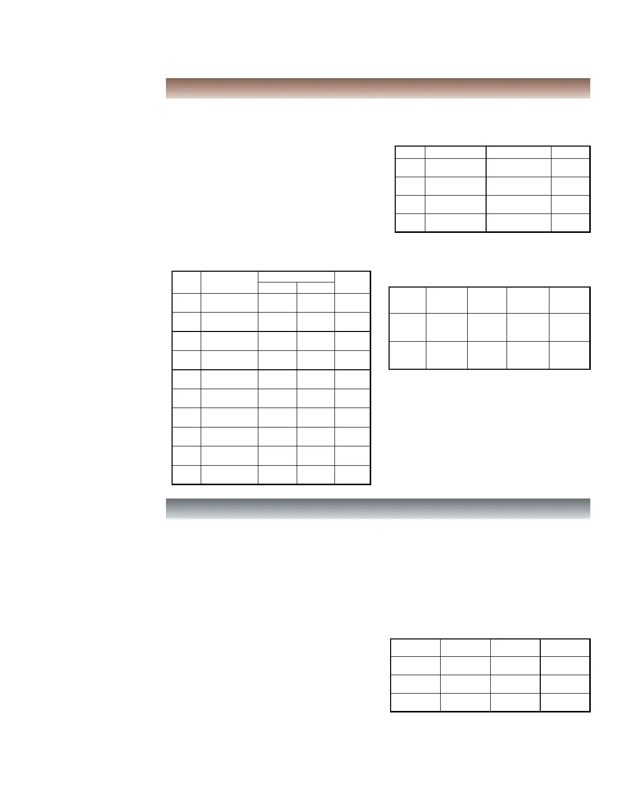
Input Specifications
Input Specifications
TYPE INPUT TYPE RANGE STANDARD
385
100 Ω platinum,
Alpha = .00385
-200 to +600°C
-328 to +1112°F
IEC 751
392
100 Ω platinum,
Alpha = .003919
-200 to +600°C
-328 to +1112°F
No official
standard
672
120 Ω nickel,
Alpha = .00672
-80 to +215°C
-112 to +419°F
No official
standard
Ohms Linear Resistance
0.0 to 320.0 Ω
N/A
INPUT
RANGE
ACCURACY * IMPEDANCE RESOLUTION
10 VDC
(-1 to 11)
1 MΩ
50 V 10 mV
20 mA DC
(-2 to 22)
10 Ω
100 mA 10 µA
MAX
CONTINUOUS
OVERLOAD
0.30 % of
reading
+0.03V
0.30 % of
reading
+0.04mA
Output Specifications
Output Specifications
1. CONTROL AND ALARM OUTPUTS:
Relay Output:
Type: Form A
Contact Rating: 3 A @ 250 VAC or 30 VDC; 1/10 HP @ 120
VAC (inductive load)
Life Expectancy: 100,000 cycles at max. load rating
(Decreasing load and/or increasing cycle time, increases
life expectancy)
Logic/SSR Output (main control output only):
Rating: 45 mA max @ 4 V min., 7 V nominal
2. MAIN CONTROL:
Control: PID or On/Off
Output: Time proportioning or DC Analog
Cycle Time: Programmable
Auto-Tune: When selected, sets proportional band, integral
time, derivative time, and output dampening time. Also sets
input filter and (if applicable) cooling gain.
Probe Break Action: Programmable
3. ALARMS: (optional) 2 relay alarm outputs.
Modes:
None
Absolute High Acting (Balanced or Unbalanced Hysteresis)
Absolute Low Acting (Balanced or Unbalanced Hysteresis)
Deviation High Acting
Deviation Low Acting
Inside Band Acting
Outside Band Acting
Heat (Alarm 1 on Analog Output models only)
Cool (Alarm 2)
Reset Action: Programmable; automatic or latched
Standby Mode: Programmable; enable or disable
Hysteresis: Programmable
Sensor Fail Response: Upscale
Annunciator: “A1” and “A2” programmable for normal or
reverse acting
4. COOLING: Software selectable (overrides Alarm 2).
Control: PID or On/Off
Output: Time proportioning
Cycle Time: Programmable
Proportional Gain Adjust: Programmable
Heat/Cool Deadband Overlap: Programmable
5. ANALOG DC OUTPUT: (optional)
Action: Control or retransmission
Update Rate: 0.1 to 250 sec
* Accuracies are expressed as ± percentages over 0 to 50 °C
ambient range after 20 minute warm-up.
** Outputs are independently jumper selectable for either 10 V
or 20 mA. The output range may be field calibrated to yield
approximately 5% overrange and a small underrange
(negative) signal.
OUTPUT
RANGE **
ACCURACY * COMPLIANCE RESOLUTION
0 to 10 V
0.3% of FS
+ ½ LSD
10 kΩ min
1/8000
0 to 20 mA
0.3% of FS
+ ½ LSD
500 Ω max
1/8000
4 to 20 mA
0.3% of FS
+ ½ LSD
500 Ω max
1/6400
 Loading...