23
PRINT OPTIONS
00 800
9600 900 800
Set the baud rate to match the other serial communications equipment on the
serial link. Normally, the baud rate is set to the highest value that all the serial
equipment is capable of transmitting and receiving.
23
BAUD RATE
ABBREVIATED PRINTING
Select for full print or Command T transmissions (meter address,
parameter data and mnemonics) or for abbreviated print transmissions
(parameter data only). This will affect all the parameters selected in the print
options. (If the meter address is 0, it will not be sent during a full transmission.)
- Enters the sub-menu to select the meter parameters to appear during a
print request. For each parameter in the sub-menu, select for that parameter
information to be sent during a print request or for that parameter information
not to be sent. A print request is sometimes referred to as a block print because
more than one parameter information (meter address, parameter data and
mnemonics) can be sent to a printer or computer as a block.
PARAMETER DESCRIPTION FACTORY MNEMONIC
Counter A
CTA
Counter B
CTB
Counter C
CTC
Rate
RTE
Max. & Min.
MIN MAX
A B C Scale Factors
SFA SFB SFC
A B C Count Load
LDA LDB LDC
1 2 3 4 Setpoints *
SP1 SP2 SP3 SP4
*Setpoints are plug-in card dependent.
DATA BIT
Select either 7 or 8 bit data word lengths. Set the word length to match the
other serial communications equipment on the serial link.
PARITY BIT
Set the parity bit to match that of the other serial communications equipment
on the serial link. The meter ignores the parity when receiving data and sets the
parity bit for outgoing data. If no parity is selected with 7 bit word length, an
additional stop bit is used to force the frame size to 10 bits.
METER ADDRESS
Enter the serial meter (node) address. The address range is dependent on the
parameter. With a single unit, configured for RLC protocol ( =
), an address is not needed and a value of zero can be used. With multiple
units (RS485 applications), a unique 2 digit address number must be assigned
to each meter.
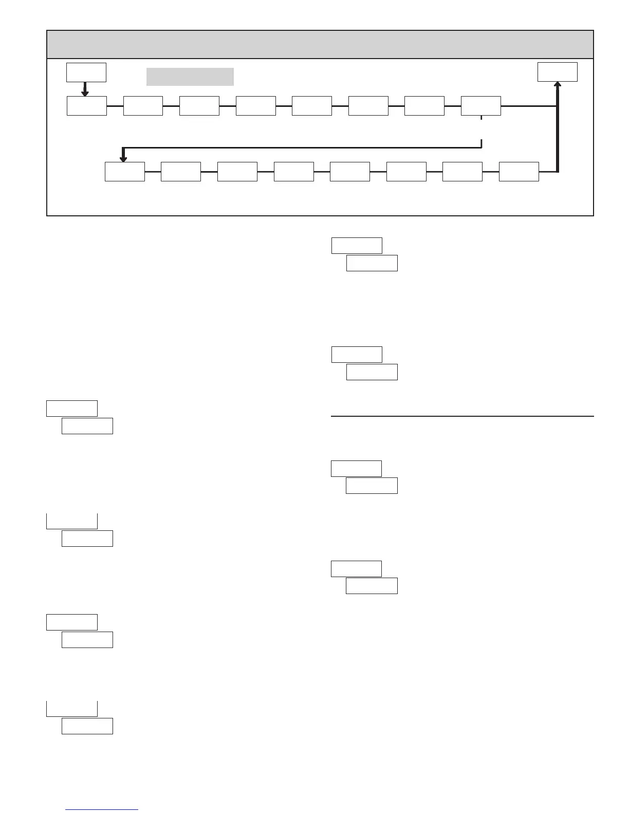
Data Bit Parity Bit Meter
Address
Transmit
Delay
bAUd
Baud
Rate
tYPE
Comms
Type
PAR
7-SrL
dAtA
Addr dELAY
Abbreviated
Printing
AbrV OPt
Pro
PAr
HILOC CNtb CNt
PAR
rAtE CNtLdSCFAC SPNt
Print
Setpoint
Values
Print
Count
Loads
Print
Scale
Factors
Print
Max/Min
Print
Rate
Print
Counter C
Print
Counter B
A CNt
Print
Counter A
YES
NO
Print
Options
PARAMETER MENU
to - Modbus
to - RLC Protocol
6.7 mOdule 7 - serial COmmuniCaTiOns parameTers ()
paXi Only
Module 7 is the programming module for the Serial Communications
Parameters. These parameters are used to match the serial settings of the PAXI
with those of the host computer or other serial device, such as a terminal or
printer. This programming module can only be accessed if an RS232 or RS485
Serial Communications card is installed.
This section also includes an explanation of the commands and formatting
required for communicating with the PAXI. In order to establish serial
communications, the user must have host software that can send and receive
ASCII characters or Modbus protocol. Red Lion’s Crimson software can be
used for configuring the PAXI (See Ordering Information). For serial hardware
and wiring details, refer to the bulletin shipped with the plug-in card.
This section does NOT apply to the DeviceNet or Profibus-DP communication
cards. For details on the operation of the Fieldbus cards, refer to the bulletin
shipped with each card.
u - Modbus RTU
- Modbus ASCII
- RLC Protocol (ASCII)
Select the desired communications protocol. Modbus protocol provides
access to all meter values and parameters. Since Modbus is included within the
PAXI, the PAX Modbus option card, PAXCDC4, should not be used. The
PAXCDC1 (RS485), or PAXCDC2 (RS232) card should be used instead.
COMMUNICATIONS TYPE
u
TRANSMIT DELAY
Following a transmit value (‘*’ terminator) or Modbus command, the PAXI
will wait this minimum amount of time before issuing a serial response.
to seconds
Parameters below only appear when Communications Type parameter
() is set to .

 Loading...