24
SERIAL MODBUS COMMUNICATIONS
Modbus Communications requires that the Serial Communications Type
Parameter (tYPE) be set to Modbus RTU (Mbrtu) or Modbus ASCII (MbASC).
PAXI CONFIGURATION USING CRIMSON AND SERIAL
COMMUNICATIONS CARD
1. Install Crimson software.
2. Install RS232 or RS485 card and connect communications cable from PAXI
to PC.
3. Supply power to PAXI.
4. Configure serial parameters to Modbus RTU (Mbrtu), 38,400 baud, address
247. (Note:These are the factory default settings.)
5. Create a new file (File, New) or open an existing PAXI V3.0+ database.
6. Configure Crimson Link options (Link, Options) to the serial port which the
communication cable is attached (in step 2).
SUPPORTED FUNCTION CODES
FC03: Read Holding Registers
1. Up to 64 registers can be requested at one time.
2. HEX <8000> is returned for non-used registers.
FC04: Read Input Registers
1. Up to 64 registers can be requested at one time.
2. Block starting point can not exceed register boundaries.
3. HEX <8000> is returned in registers beyond the boundaries.
4. Input registers are a mirror of Holding registers.
FC06: Preset Single Register
1. HEX <8001> is echoed back when attempting to write to a read only register.
2. If the write value exceeds the register limit (see Register Table), then that
register value changes to its high or low limit. It is also returned in the
response.
FC16: Preset Multiple Registers
1. No response is given with an attempt to write to more than 64 registers at a
time.
2. Block starting point cannot exceed the read and write boundaries (40001-
41280).
3. If a multiple write includes read only registers, then only the write registers
will change.
4. If the write value exceeds the register limit (see Register Table), then that
register value changes to its high or low limit.
FC08: Diagnostics
The following is sent upon FC08 request:
Module Address, 08 (FC code), 04 (byte count), “Total Comms” 2 byte count,
“Total Good Comms” 2 byte count, checksum of the string
“Total Comms” is the total number of messages received that were addressed
to the PAXI. “Total Good Comms” is the total messages received by the
PAXI with good address, parity and checksum. Both counters are reset to
0 upon response to FC08 and at power-up.
FC17: Report Slave ID
The following is sent upon FC17 request:
RLC-PAXI_V3 <a><b><0300h><0040h><0040h><0010h>
<a> = SP Card Status. “0”-None, “2”-Dual, “4”-Quad
<b> = Linear Card Status. “0”-Not Installed, “1”-Installed
<0300h> = Software Version Number (e.g. 3.00)
<0040h><0040h> = Max Register Reads/Writes (64)
<0010h> = Number of GUID/Scratch Pad Registers (16)
SUPPORTED EXCEPTION CODES
01: Illegal Function
Issued whenever the requested function is not implemented in the meter.
02: Illegal Data Address
Issued whenever an attempt is made to access a single register that does not
exist (outside the implemented space) or to access a block of registers that falls
completely outside the implemented space.
03: Illegal Data Value
Issued when an attempt is made to read or write more registers than the meter
can handle in one request.
07: Negative Acknowledge
Issued when a write to a register is attempted with an invalid string length.
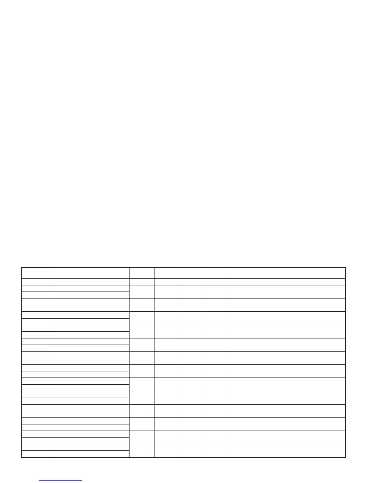
PAXI MODBUS REGISTER TABLE
This table shows the most commonly used registers for the PAXI. The complete register table listing is available at http://www.redlion.net.
Values less than 65,535 will be in (Lo word). Values greater than 65,535 will continue into (Hi word). Negative values are represented by two’s complement of the
combined (Hi word) and (Lo word). The PAXI should not be powered down while parameters are being changed. Doing so may corrupt the non-volatile memory
resulting in checksum errors.
REGISTER
ADDRESS
REGISTER NAME LOW LIMIT HIGH LIMIT
FACTORY
SETTING
ACCESS COMMENTS
FREQUENTLY USED REGISTERS
40001 Counter A Value (Hi word)
-99999999 999999999 0 Read/Write 1 = 1 Display Unit
40002 Counter A Value (Lo word)
40003 Counter B Value (Hi word)
-99999999 999999999 0 Read/Write
1 = 1 Display Unit
40004 Counter B Value (Lo word)
40005 Counter C Value (Hi word)
-99999999 999999999 0 Read/Write 1 = 1 Display Unit
40006 Counter C Value (Lo word)
40007 Rate Value (Hi word)
0 99999 0 Read/Write 1 = 1 Display Unit
40008 Rate Value (Lo word)
40009 Min (Lo) Value (Hi word)
0 99999 0 Read/Write 1 = 1 Display Unit
40010 Min (Lo) Value (Lo word)
40011 Max (Hi) Value (Hi word)
0 99999 0 Read/Write 1 = 1 Display Unit
40012 Max (Hi) Value (Lo word)
40013 Counter A Scale Factor (Hi word)
1 999999 100000 Read/Write Active List (A or B)
40014 Counter A Scale Factor (Lo word)
40015 Counter B Scale Factor (Hi word)
1 999999 100000 Read/Write Active List (A or B)
40016 Counter B Scale Factor (Lo word)
40017 Counter C Scale Factor (Hi word)
1 999999 100000 Read/Write Active List (A or B)
40018 Counter C Scale Factor (Lo word)
40019 Counter A Count Load (Hi word)
-99999 999999 500 Read/Write Active List (A or B)
40020 Counter A Count Load (Lo word)
40021 Counter B Count Load (Hi word)
-99999 999999 500 Read/Write Active List (A or B)
40022 Counter B Count Load (Lo word)
40023 Counter C Count Load (Hi word)
-99999 999999 500 Read/Write Active List (A or B)
40024 Counter C Count Load (Lo word)
40025 Setpoint 1 Value (Hi word)
-199999 999999 100 Read/Write Active List (A or B)
40026 Setpoint 1 Value (Lo word)

 Loading...