25
REGISTER
ADDRESS
REGISTER NAME LOW LIMIT HIGH LIMIT
FACTORY
SETTING
ACCESS COMMENTS
40027 Setpoint 2 Value (Hi word)
-199999 999999 200 Read/Write Active List (A or B)
40028 Setpoint 2 Value (Lo word)
40029 Setpoint 3 Value (Hi word)
-199999 999999 300 Read/Write Active List (A or B)
40030 Setpoint 3 Value (Lo word)
40031 Setpoint 4 Value (Hi word)
-199999 999999 400 Read/Write Active List (A or B)
40032 Setpoint 4 Value (Lo word)
Manual Mode Registers
40036 Manual Mode Register (MMR) 0 31 0 Read/Write
Bit State: 0 = Auto Mode, 1 = Manual Mode Bit 4 = S1, Bit 3
= S2, Bit 2 = S3, Bit 1 = S4, Bit 0 = Linear Output
40037 Analog Output Register (AOR) 0 4095 0 Read/Write
Linear Output Card written to only if Linear Output is in
Manual Mode (MMR bit 0 = 1).
40038 Setpoint Output Register (SOR) 0 15 N/A Read/Write
Status of Setpoint Outputs. Bit State: 0=Off, 1=On.
Bit 3 = S1, Bit 2 = S2, Bit 1 = S3, Bit 0 = S4.
Outputs can only be activated/reset with this register when the
respective bits in the Manual Mode Register (MMR) are set.
40039 Reset Output Register 0 15 0 Read/Write
Bit State: 1= Reset Output, bit is returned to zero following
reset processing; Bit 3 = S1, Bit 2 = S2, Bit 1 = S3, Bit 0 = S4
SERIAL RLC PROTOCOL COMMUNICATIONS
RLC Communications requires the Serial Communications Type Parameter
(tYPE) be set to RLC Protocol (rLC).
SENDING SERIAL COMMANDS AND DATA TO THE METER
When sending commands to the meter, a string containing at least one
command character must be constructed. A command string consists of a
command character, a value identifier, numerical data (if writing data to the
meter) followed by a command terminator character * or $. The <CR> is also
available as a terminator when Counter C is in the SLAVE mode.
Command Chart
COMMAND DESCRIPTION NOTES
N Node (Meter)
Address
Specifier
Address a specific meter. Must be followed by a
two digit node address. Not required when
address = 00.
T Transmit Value
(read)
Read a register from the meter. Must be followed
by register ID character
V Value Change
(write)
Write to register of the meter. Must be followed by
register ID character and numeric data.
R Reset Reset a register or output. Must be followed by
register ID character.
P Block Print
Request
Initiates a block print output. Registers are defined
in programming.
Command String Construction
The command string must be constructed in a specific sequence. The meter
does not respond with an error message to invalid commands. The following
procedure details construction of a command string:
1. The first characters consist of the Node Address Specifier (N) followed by a
1 or 2 character address number. The address number of the meter is
programmable. If the node address is 0, this command and the node address
itself may be omitted. For node address 1 through 9, a leading zero character
is not required. (The only exception is a numeric transmission when Counter
C is set for slave mode.) This is the only command that may be used in
conjunction with other commands.
2. After the optional address specifier, the next character is the command
character.
3. The next character is the Register ID. This identifies the register that the
command affects. The P command does not require a Register ID character.
It prints according to the selections made in print options.
4. If constructing a value change command (writing data), the numeric data is
sent next.
5. All command strings must be terminated with the string termination
characters *, $ or when Counter C is set for slave mode <CR>. The meter
does not begin processing the command string until this character is received.
See Timing Diagram figure for differences between terminating characters.
Sending Numeric Data
Numeric data sent to the meter must be limited to the digit range shown under
transmit details in the Register Identification Chart. Leading zeros are ignored.
Negative numbers must have a minus sign. The meter ignores any decimal point
and conforms the number to the scaled resolution. (For example: the meter’s
scaled decimal point position = 0.0 and 25 is written to a register. The value of
the register is now 2.5.
Note: Since the meter does not issue a reply to value change commands, follow
with a transmit value command for readback verification.
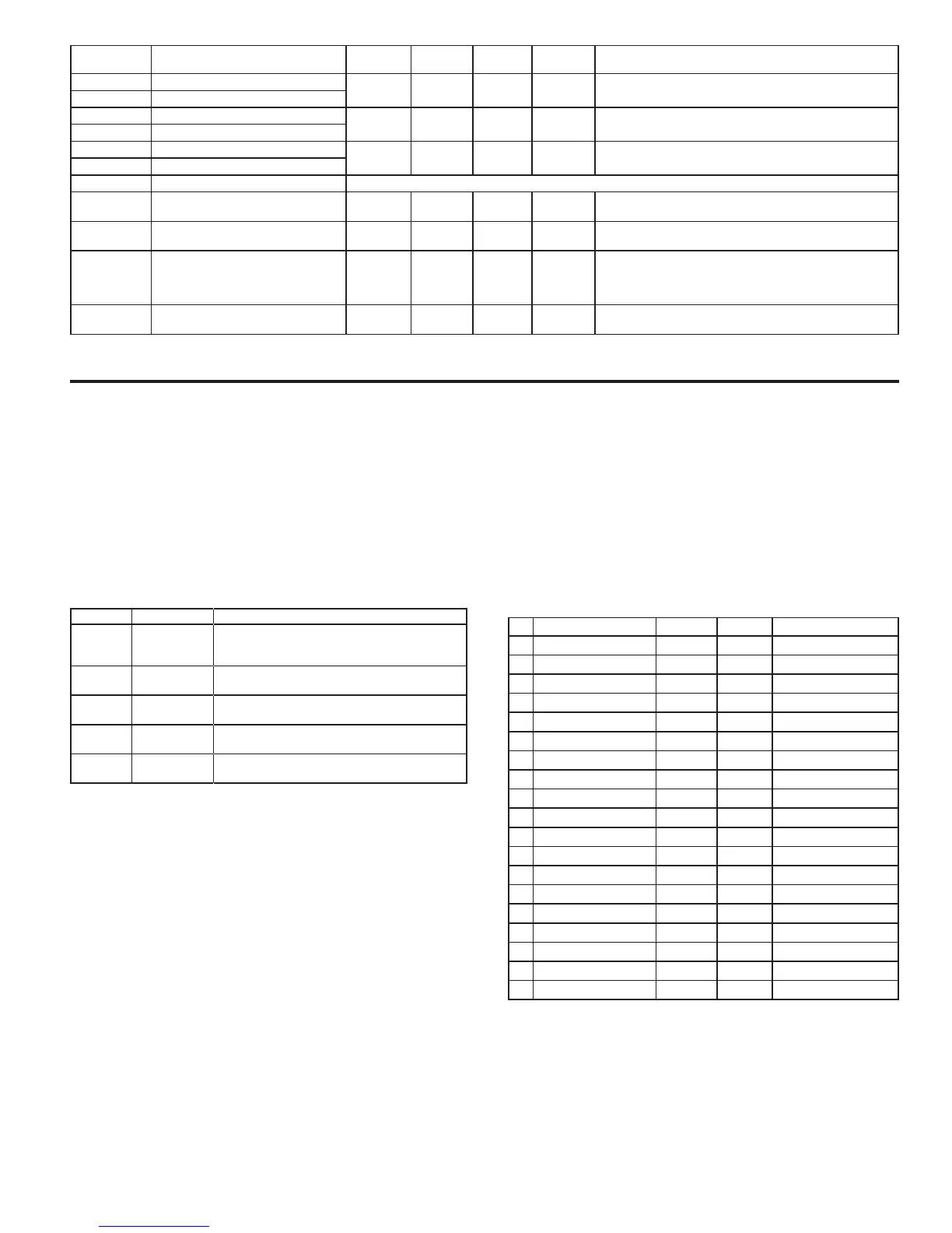
Register Identification Chart
ID VALUE DESCRIPTION MNEMONIC COMMAND TRANSMIT DETAILS
A Count A CTA T, V, R 6 digit (V), 8 digit (T)
B Count B CTB T, V, R 6 digit (V), 8 digit (T)
C Count C CTC T, V, R 6 digit (V), 8 digit (T)
D Rate RTE T, V 5 digit, positive only
E Min (Lo) Value MIN T, V, R 6 digit, positive only
F Max (Hi) Value MAX T, V, R 6 digit, positive only
G Scale Factor A SFA T, V 6 digit, positive only
H Scale Factor B SFB T, V 6 digit, positive only
I Scale Factor C SFC T, V 6 digit, positive only
J Counter Load A LDA T, V 5 negative / 6 positive
K Counter Load B LDB T, V 5 negative / 6 positive
L Counter Load C LDC T, V 5 negative / 6 positive
M Setpoint 1 SP1 T, V, R 5 negative / 6 positive
O Setpoint 2 SP2 T, V, R 5 negative / 6 positive
Q Setpoint 3 SP3 T, V, R 5 negative / 6 positive
S Setpoint 4 SP4 T, V, R 5 negative / 6 positive
U Auto/Manual Register MMR T, V 0 – auto, 1 - manual
W Analog Output Register AOR T, V 0 – 4095 normalized
X Setpoint Register SOR T, V 0 – not active, 1 – active
Command String Examples:
1. Address = 17, Write 350 to Setpoint 1.
String: N17VM350$
2. Address = 5, Read Count A value.
String: N5TA*
3. Address = 0, Reset Setpoint 4 output.
String: RS*

 Loading...