11
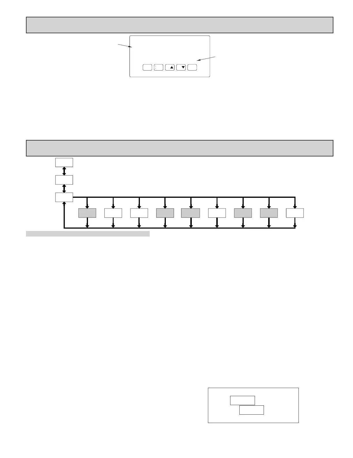
5.0 reviewing The frOnT buTTOns and display
Counter
Readout
Legends*
Setpoint Alarm
Annunciators
RSTDSP
PAR
F
1
F2
A
C
B
SP1 SP3
SP2
SP4
KEY DISPLAY MODE OPERATION PROGRAMMING MODE OPERATION
DSP Index display through the selected displays. Quit programming and return to Display Mode
PAR Access Programming Mode Store selected parameter and index to next parameter
F1 Function key 1; hold for 3 seconds for Second Function 1 ** Increment selected parameter value or selections
F2
Function key 2; hold for 3 seconds for Second Function 2 ** Decrement selected parameter value or selections
RST Reset (Function key) *** Advances digit location in parameter values
* Counters B, and C are locked out in Factory Settings (PAXC and PAXI only).
** Factory setting for the F1, and F2 keys is NO mode.
*** Factory setting for the RST key is (Reset Display).
PROGRAMMING MODE ENTRY (PAR KEY)
The meter normally operates in the Display Mode. No parameters can be
programmed in this mode. The Programming Mode is entered by pressing the
PAR key. If it is not accessible then it is locked by either a security code, or a
hardware lock.
Two types of programming modes are available. Quick Programming Mode
permits only certain parameters to be viewed and/or modified. All meter
functions continue to operate except the front panel keys change to Programming
Mode Operations. Quick Programming Mode is configured in Module 3. Full
Programming Mode permits all parameters to be viewed and modified. In this
mode, incoming counts may not be recognized correctly, the front panel keys
change to Programming Mode Operations and certain user input functions are
disabled. Throughout this document, Programming Mode (without Quick in
front) always refers to “Full” Programming.
MODULE ENTRY (ARROW & PAR KEYS)
The Programming Menu is organized into nine modules. These modules group
together parameters that are related in function. The display will alternate between
and the present module. The arrow keys (F1 and F2) are used to select
the desired module. The displayed module is entered by pressing the PAR key.
MODULE MENU (PAR KEY)
Each module has a separate module menu (which is shown at the start of each
module discussion). The PAR key is pressed to advance to a particular parameter
to be changed, without changing the programming of preceding parameters.
After completing a module, the display will return to . Programming may
continue by accessing additional modules.
SELECTION / VALUE ENTRY (ARROW & PAR KEYS)
For each parameter, the display alternates between the present parameter and
the selections/value for that parameter. The arrow keys (F1 and F2) are used
to move through the selections/values for that parameter. Pressing the PAR key,
stores and activates the displayed selection/value. This also advances the meter
to the next parameter.
For numeric values, the RST key may be used to select a specific digit to be
changed. Once a digit is selected, the arrow keys are used to increment or
decrement that digit to the desired number.
PROGRAMMING MODE EXIT (DSP KEY or at PAR KEY)
The Programming Mode is exited by pressing the DSP key (from anywhere
in the Programming Mode) or the PAR key (with displayed). This will
commit any stored parameter changes to memory and return the meter to the
Display Mode. If a parameter was just changed, the PAR key should be pressed
to store the change before pressing the DSP key. (If power loss occurs before
returning to the Display Mode, verify recent parameter changes.)
PROGRAMMING TIPS
It is recommended to start with Module 1 for counting and Module 4 for rate.
If lost or confused while programming, press the DSP key and start over. When
programming is complete, it is recommended to record the parameter
programming on the Parameter User Chart and lock out parameter programming
with a user input or lock-out code.
FACTORY SETTINGS
Factory Settings may be completely restored in Module 9. This is a good
starting point for programming problems. Most parameters can be left at their
Factory Settings without affecting basic start-up.
ALTERNATING SELECTION DISPLAY
In the explanation of the modules, the following dual display with arrows will
appear. This is used to illustrate the display alternating between the parameter
on top and the parameter’s Factory Setting on the bottom. In most cases,
selections and values for the parameter will be listed on the right.
6.0 prOgramming The meTer
Parameters
Input
Rate
4-rtE
Parameters
& B Input
1-INP
Pro
DISPLAY
MODE
Lock-out
Key
2-FNC
Parameters
3-LOC
Parameters
Function
Program
Communication(Alarm)Counter C
6-SPt5-CtrC 7-SrL
Parameters
Setpoint*Serial*
ServiceOutput
9-FCS8-AnA
Parameters
FactoryAnalog*
Parameters Parameters Operations
Counter A
User Input/
NO
* Only accessible with appropriate plug-in card.
PAR
F1/F2
Keys
Display/
PAR PAR PAR PAR PARPAR PARPAR PAR
OVERVIEW
PROGRAMMING MENU
Indicates Program Mode Alternating Display
Factory Settings are shown.
Parameter
Selection/Value
Shaded areas represent program access that is model dependent.

 Loading...