12
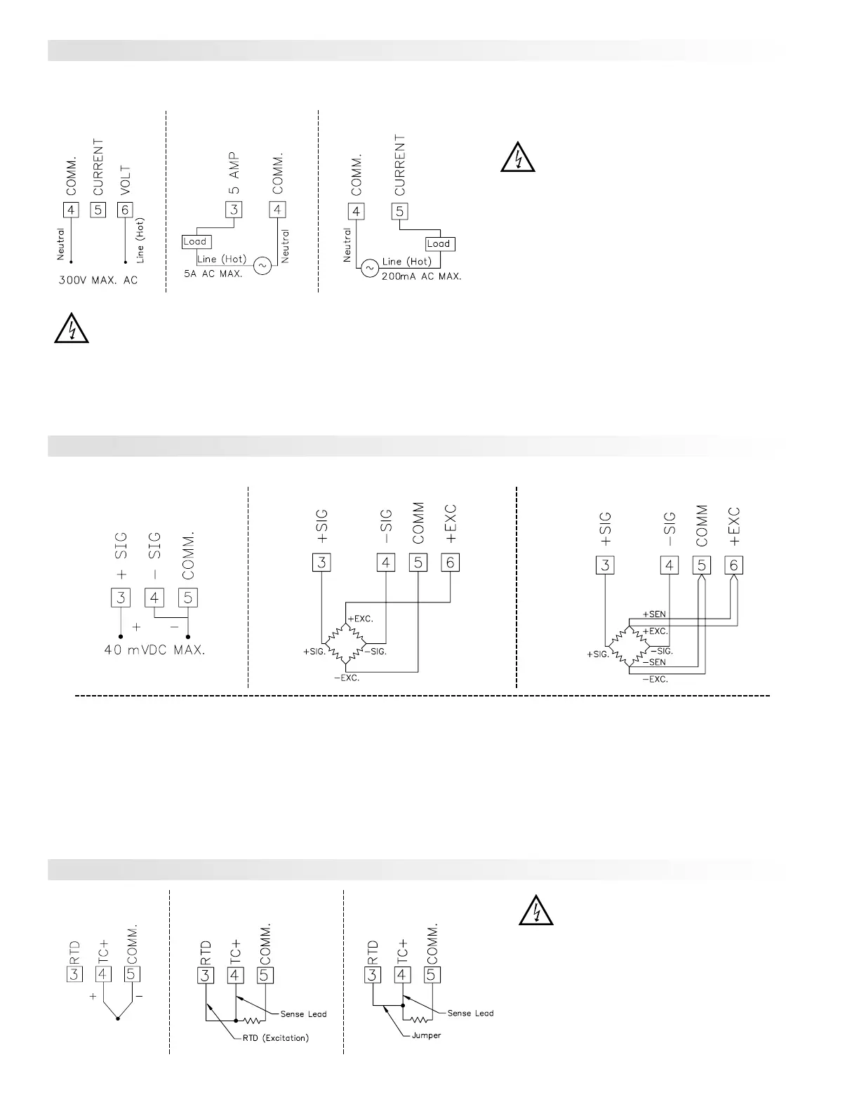
4-Wire Bridge Input
2-Wire Single
Ended Input
6-Wire Bridge Input
DEADLOAD COMPENSATION
In some cases, the combined deadload and liveload output may exceed the
range of the 24 mV input. To use this range, the output of the bridge can be offset
a small amount by applying a fixed resistor across one arm of the bridge. This
shifts the electrical output of the bridge downward to within the operating range
of the meter. A 100 K ohm fixed resistor shifts the bridge output approximately
-10 mV (350 ohm bridge, 10 V excitation).
Connect the resistor between +SIG and -SIG. Use a metal film resistor with a
low temperature coefficient of resistance.
BRIDGE COMPLETION RESISTORS
For single strain gage applications, bridge completion resistors must be
employed externally to the meter. Only use metal film resistors with a low
temperature coefficient of resistance.
Load cells and pressure transducers are normally implemented as full
resistance bridges and do not require bridge completion resistors.
Before connecting signal wires, the Input Range Jumper should be verified for proper position.
PAXT INPUT SIGNAL WIRING
3-Wire RTD
Thermocouple
2-Wire RTD
CAUTION: Sensor input common is NOT isolated
from user input common. In order to preserve the
safety of the meter application, the sensor input
common must be suitably isolated from hazardous
live earth referenced voltages; or input common
must be at protective earth ground potential. If not,
hazardous live voltage may be present at the User
Inputs and User Input Common terminals.
Appropriate considerations must then be given to the
potential of the user input common with respect to
earth common; and the common of the isolated plug-
in cards with respect to input common.
CAUTION:
1. Where possible, connect the neutral side of the signal (including current shunts) to the input common of the meter. If the input signal is sourced from
an active circuit, connect the lower impedance (usually circuit common) to the input signal common of the meter.
2. For phase-to-phase line monitoring where a neutral does not exist, or for any other signal input in which the isolation voltage rating is exceeded, an isolating potential
transformer must be used to isolate the input voltage from earth. With the transformer, the input common of the meter can then be earth referenced for safety.
3. When measuring line currents, the use of a current transformer is recommended. If using external current shunts, insert the shunt in the neutral return line. If the
isolation voltage rating is exceeded, the use of an isolating current transformer is necessary.
Current Signal (Amps)Voltage Signal Current Signal (Milliamps)
Before connecting signal wires, the Signal, Input Range and Couple Jumpers
should be verified for proper position.
CAUTION: Connect only one input signal range to the
meter. Hazardous signal levels may be present on
unused inputs.
CAUTION: The isolation rating of the input common of the
meter with respect to the option card commons and the
user input common Terminal 8 (If used) is 125 Vrms; and
250 Vrms with respect to AC Power (meter Terminals 1 &
2). To be certain that the ratings are not exceeded, these
voltages should be verified by a high-voltage meter before
wiring the meter.
PAXS INPUT SIGNAL WIRING
PAXH INPUT SIGNAL WIRING
 Loading...


