List of Figures
Figure 1: Drip Loop .............................................................................................................5
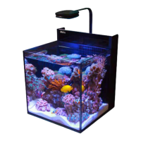
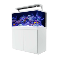
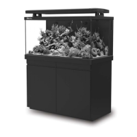
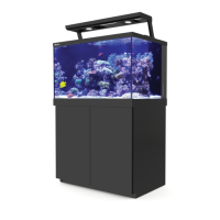
Figure 2: MAX contents ......................................................................................................7
Figure 3: Biological filter....................................................................................................9
Figure 4: Carbon filter.........................................................................................................9
Figure 5: Circulation pump.................................................................................................9
Figure 6: Installing circulation pumps ...............................................................................10
Figure 7: Heater ..................................................................................................................10
Figure 8: Threading the heater cord ................................................................................10
Figure 9: Protein skimmer parts........................................................................................11
Figure 10: Skimmer assembled.........................................................................................11
Figure 11: Inserting protein skimmer ...............................................................................12
Figure 12: Mechanical filtration material .........................................................................12
Figure 13: Inserting filter comb.........................................................................................12
Figure 14: Attaching and positioning filter shutter..........................................................13
Figure 15: Light tubes ........................................................................................................13
Figure 16: Inserting bulb....................................................................................................13
Figure 17: Positioning lighting control cover ...................................................................14
Figure 18: Positioning skimmer hood ...............................................................................14
Figure 19: Attaching the skimmer hood...........................................................................14
Figure 20: Securing the hood supports.............................................................................15
Figure 21: Lowering the hood ...........................................................................................15
Figure 22: Skimmer collection cup....................................................................................15
Figure 23: Attaching the skimmer collection cup ............................................................15
Figure 24: Power center.....................................................................................................16
Figure 25: Removing the splash cover .............................................................................16
Figure 26: Replacing the splash cover ..............................................................................16
Figure 27: Inserting power center.....................................................................................17
Figure 28: Control panel.....................................................................................................17
Figure 29: Timer and switch ..............................................................................................17
Figure 30: Removing the splash cover .............................................................................17
Figure 31: Water circulation...............................................................................................21