1 PRODUCT FUNCTION
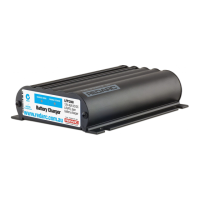
1.3 Display Panel
The BCDC1220 has three Battery Type Settings available. These settings enable
optimal charging profi les for the auxiliary battery. The battery type selected is
displayed via the LEDs on the front panel in the section ‘Battery Type’. In addition
to the battery type, the status of the charger is indicated via three LEDs. The
‘Charging Status’ shows when the unit is in BOOST, ABSORPTION or FLOAT. In
order to give more information, the applicable LED will fl ash to indicate the output
by the unit. The longer the fl ash, the more current the charger is putting out. If
the LED is ON solid, then the unit is supplying a full 20A to the auxiliary battery.
Standby mode is entered when the unit is not charging. In this mode, the Battery
Type LED will blink approx once per second; the charging status LEDs will be off.
In this mode, if the battery type wire is moved then the selected battery type will
update.
2 INSTALLATION
1 Mount the unit to a fl at surface close to the auxiliary battery and away from any
heat sources.
The unit will operate optimally below 55°C with good airfl ow. At higher
temperatures the unit will de-rate output current.
2 Wire into vehicle as per the applicable diagram on the next pages, and following
the steps below.
The BCDC1220 is connected using 5 wires, listed below:
• Source Select Blue
• Battery Type Orange
• Input Battery Positive Red 30A Fuse (not supplied)
• Common Ground Black
• Output Battery Positive Brown 30A Fuse (not supplied)
4
RoHS
Compliant
BCDC1220
12V 20A DC/DC
3 stage
battery charger
Designed and made in Australia
BATTERY TYPE CHARGE STATUS
AGM/gel
Standard
Calcium
Boost
Absorption
Float
Figure 1.3.1 - BCDC1220 Front Panel
 Loading...