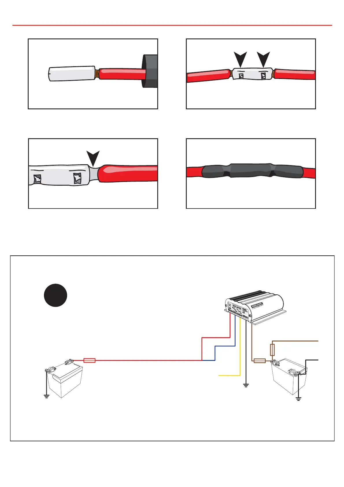
12V
Loads
Load
Fuse
30A
Fuse
All ground points must
be connected to chassis
earth.
Auxiliary
Battery
Battery
config
wire
Start
Battery
30A
Fuse
Note: Power wires must be
at least 3mm² and must be
crimped using an
appropriate crimp tool.
INPUT
7
2 INSTALLATION
Figure 2.2 - Standard setup for a 12V Start Battery
Crimp here.
Solder here.
Figure 2.1 - Ensuring a good wiring connection
Slip heatshrink over wire and insert wires into
butt splice. Keep heatshrink away from joint until
after soldering is complete and has cooled.
Crimp both wires to the butt splice using indent
type crimpers.
Solder the wires to the butt splice. Ensure that a
good connection is made.
Wait for the butt splice to cool, slip heatshrink
over the joint and heat.
 Loading...