6
2 INSTALLATION
2.2 BLUE wire - Input Trigger
The BLUE wire is provided to select the units input trigger behaviour. This wire is
monitored at all times.
2.1.1 BCDC1220
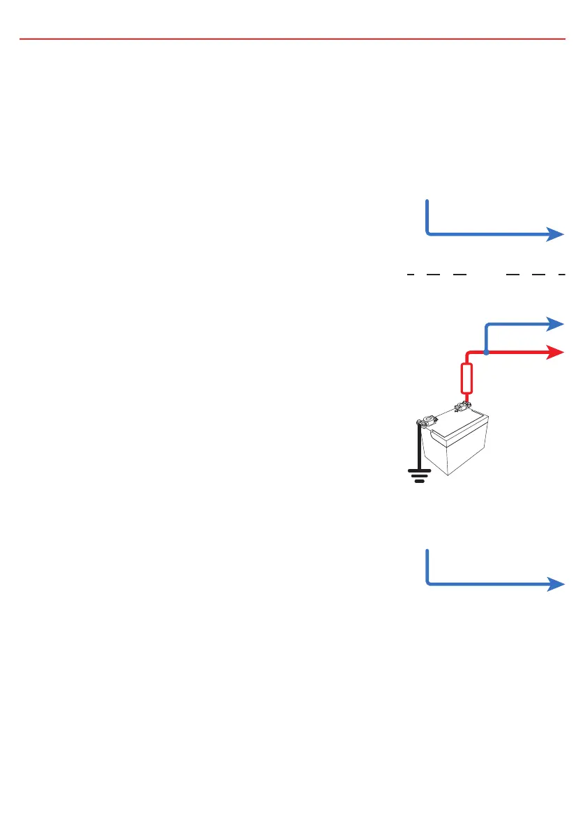
To charge from a 12V alternator simply connect the
BLUE ‘Input Trigger’ wire to the RED ‘Input Positive’
wire. Alternatively, the BLUE ‘Input Trigger’ wire can
be connected to the vehicle ignition.
NOTE: To charge from a 24V alternator the BLUE ‘Input
Trigger’ wire must be connected to the vehicle ignition.
2.1.2 BCDC1220-IGN
To charge from either a 12V or 24V Variable Voltage or
Smart Alternator system the BLUE ‘Input Trigger’ wire
must always be connected to the vehicle ignition.
Vehicle
Ignition
Blue Wire
OR
Vehicle
Ignition
12V Starter
battery only
12V OR 24V
Starter battery.
Blue Wire
Blue Wire
Red Wire
Input
Source
Positive
Midi
Fuse
 Loading...


