R
Roger BurtonAug 8, 2025
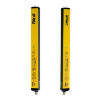
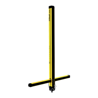
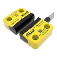
What to do if Reer Security Sensors system stoppage?
- MmoracharlesAug 8, 2025
If the Reer Security Sensors system stops, switch it off and on again. This helps determine if temporary electromagnetic disturbances caused the issue.