

C
Cynthia Mosley DVMAug 20, 2025
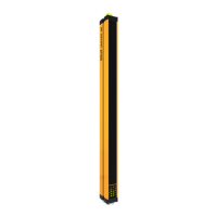
What to do if muting light is not present or fault in Reer JANUS?
- KKathy SchmidtAug 20, 2025
If the muting light is not present or faulty on your Reer Security Sensors, verify that the MUTING lamp is present and working efficiently.