30 8540573 • 16/09/2016 • Rev.20
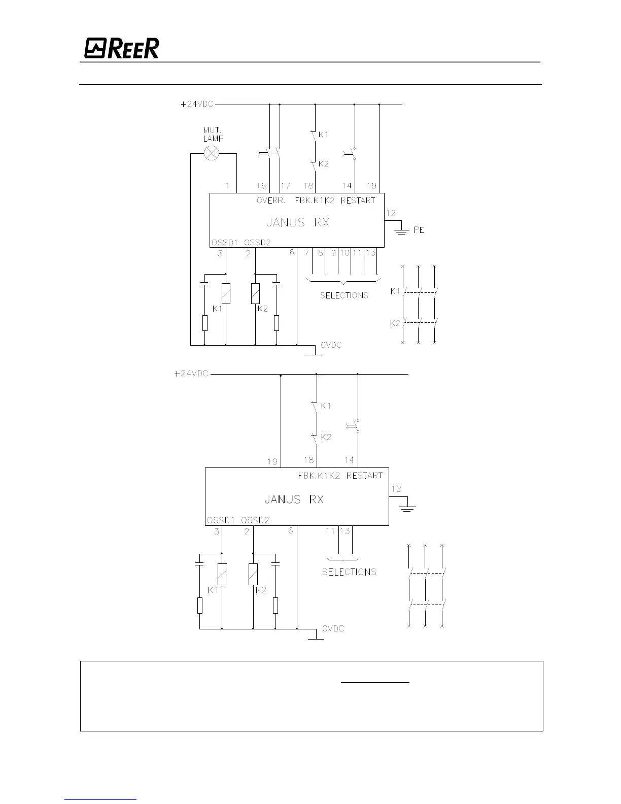
EXAMPLE OF CONNECTION WITH EXTERNAL CONTACTORS K1/K2 WITH START/RESTART INTERLOCK ACTIVATED
Figura 29
In order to assure a correct barrier operation, it is necessary to connect the pins 2 and
4 of the Emitter according to table 6 (page 20) and to the "TEST FUNCTION" paragraph of
page 26. For correct operation (in the case of JANUS "M" without the use of Muting) the
muting light must be connected (pin 1) and the Muting mode must be configured correctly
(pin 7-8-9-10) following the indications in Table 13.
 Loading...