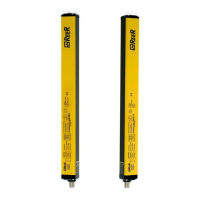
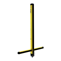
EOS4 SAFETY LIGHT CURTAIN
16 8540733 • 23/03/2016 • Rev.17
Emitter connections
EOS4A - EOS4X (with integrated control functions) - EOS4XM (MASTER models)
M12 5-pin primary connectors.
Light curtain configuration
complying with the EN61131-2 standard
(ref. Table 5)
Light curtain configuration
complying with the EN61131-2 standard
(ref. Table 5)
Table 4 - M12, 5 pin
Master/Standard/with integrated control functions TX
Table 5 – Range and TEST selection
For correct operation of the light curtain, pins 2 and 4 of the Emitter must be
connected as indicated in Table 5.
EOS4XS - EOS4XS2 (SLAVE/SLAVE2 models) - M12, 5-pin primary connector.
Communication
MASTER-SLAVE
Communication
MASTER-SLAVE
Table 6 - M12, 5-pin Primary Slave TX
EOS4XM (MASTER models) – M12, 5-pin secondary connector.
EOS4XS2 (SLAVE2 models) – M12, 5-pin secondary connector.
Communication
MASTER-SLAVE
Communication
MASTER-SLAVE
Table 7 - M12, 5-pin Secondary TX
 Loading...