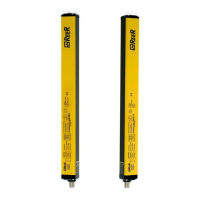
EOS4 SAFETY LIGHT CURTAIN
24 8540733 • 23/03/2016 • Rev.17
OPERATION AND TECHNICAL DATA
Light signals
The leds on the Emitter and Receiver light up according to system operating conditions.
Refer to the tables below to identify the various indications (ref. Figure 25).
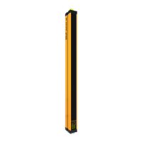
Figure 25 - Light signals
Emitter light signals
System power-on. Initial TEST.
System power-on. HIGH working range selected.
FAIL condition (Table 19)
Normal operating condition
Table 13 – TX light signals
Receiver light signals
System power-on. Initial TEST.
FAIL condition (Table 19)
Table 14 – RX light signals EOS4 A / EOS4 Slave
System power-on. Initial TEST
FAIL condition (Table 19)
Table 15 – RX light signals EOS4 X (With integrated control functions)
The type of fault is identified by the number of flashes (see chapter)
 Loading...