9
Equipment Operation
GALVANIC ISOLATOR MONITOR SYSTEM
One of the most important elements in using shore power
aboard a vessel is that while it is plugged into the dock
the bonding system needs to be electrically connected to
earth.
Missing this earth connection allows the bonding system
to be potentially “hot”. If this occurs, the chance for elec-
trocution to anyone in the water or boarding the boat dra-
matically increases.
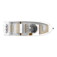
Your vessel utilizes a galvanic isolator. Its purpose is to
allow the separation of the bonding system from the dock
and other boats at low voltages (less than 1.4 volts) but to
keep it connected to the shore ground at high voltage po-
tentials. Remember, the zinc anodes installed on the ves-
sel protect your boat only. For this reason the name “zinc
saver” is a term sometimes used to describe the galvanic
isolator.
This type of galvanic isolator connects to your electrical/
bonding system for less than 20 seconds during a day. This
limits the negative effects on the ship’s bonding system.
The monitor performs various tests when connected to
shore power or activated by the push to test button or
every 6 hours after that. After it does a “self-test” then it
tests the ground wire continuity and the galvanic isolator
and shows the results on the monitor head. During the
self test the LED’s will light on the panel. The isolator is
normally found behind the AC/DC panel. It is consid-
ered a dealer serviceable item.
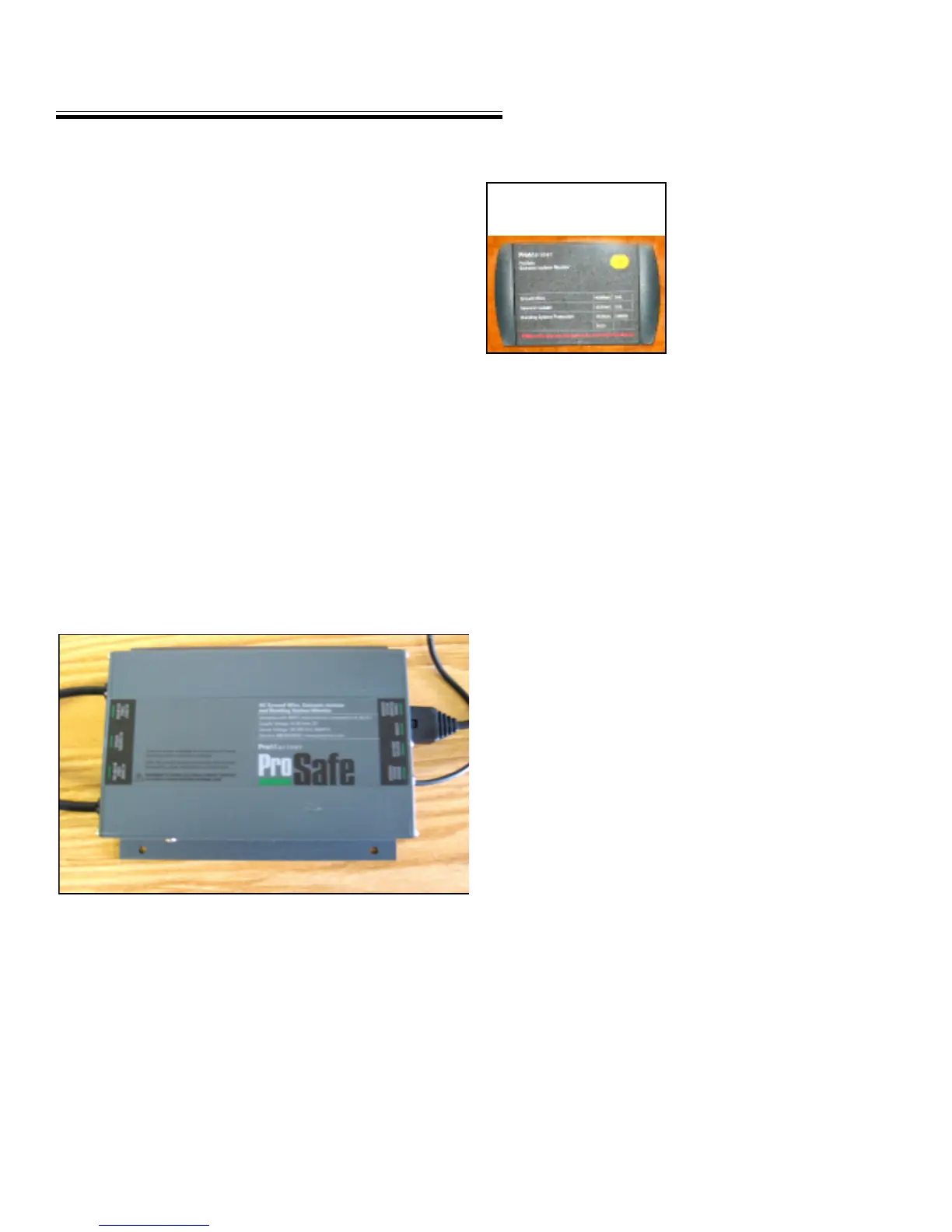
MONITOR PANEL
To use the monitor in the au-
tomatic mode, turn the main
AC panel breaker and the tran-
som shore power breaker to
the off position. Turn the
dockside breaker to the off
position.
Connect both ends of both
shore power cords. Turn on
the dockside breaker. The monitor will activate itself. It
will perform the self-test. Then it will display the ground
wire condition and the galvanic isolator in about 20 sec-
onds. This test will be completed every 6 hours.
If the “fail” icon lights up on either the ground wire or galvanic
isolator displays an ungrounded bonding system exists and should
be considered dangerous. Disconnect the shore power cords
after turning the dockside breaker off and call a profes-
sional electrical technician to troubleshoot and repair the
situation.
To use the monitor in the manual mode, press the “test”
button on the display panel. A sequential set of LED’s will
light up indicating the status of the ground wire and gal-
vanic isolator as either pass or fail.
If the “fail” icon lights up on either the ground wire or galvanic
isolator displays an ungrounded bonding system exists and should
be considered dangerous. Disconnect the shore power cords
after turning the dockside breaker off and call a profes-
sional electrical technician to troubleshoot and repair the
situation.
Note: The monitor will display both shore power 1 and 2
systems.
Ground Wire “Normal”- The shore power ground wire
has been tested and is connected to neutral through the
shore side ground circuit.
MONITOR LED DISPLAY ANALYSIS
GALVANIC ISOLATOR