4
Chapter 5
DASH COMPONENT OPERATION
Below is a description of the main dash switched
components. This includes the helm and DC switch panel
located to the starboard side of the helm seat. Read and
understand their operation. Your dash may not include
some of the discussed control devices. Refer to more in
depth instructions to supplement this information which
can be found in the owner’s document box.
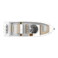
Battery Parallel Switch
The battery parallel switch
provides starting power in the
event one or more of the
batteries are discharged. Upon
starting the engines press the
parallel switch to energize the
circuit via a charged battery. In
the event the battery parallel
switch is used make sure you
investigate the reason the
circuit was initially discharged.
A breaker protects the parallel
switch.
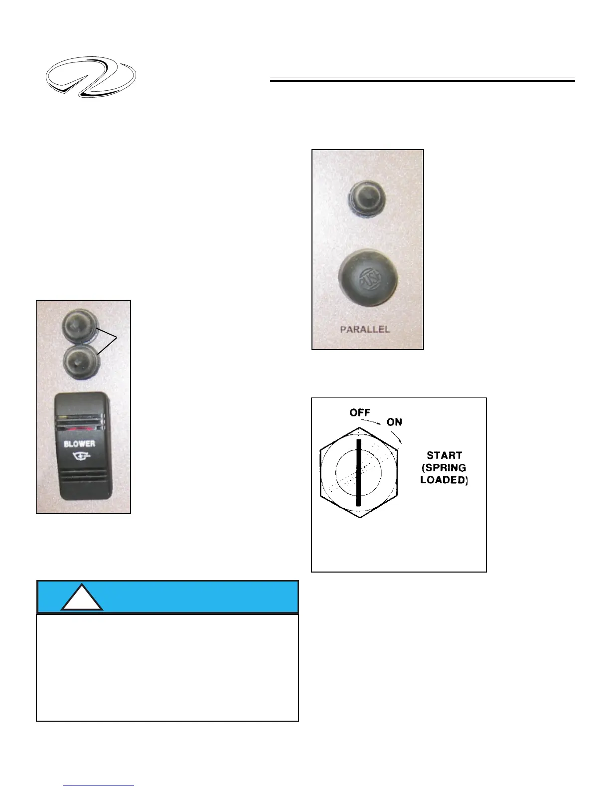
Blower
This switch controls the two bilge
blowers. The blower must be
activated to the “on” position at
least 4 minutes prior to starting the
engines. This procedure assists in
evacuating any fumes in the bilge
area. The blower should be used
below cruising speeds. Besides
activating the blower switch a visual
check should be done before
starting the engines by lifting the
engine inspection hatch and
“sniffing” for fumes in the bilge.
Notice that each blower uses
individual circuit protection as a
safety measure. A red icon located
in the center of the switch lights up when the blower is
activated.
WARNING
!
GASOLINE VAPORS CAN EXPLODE!
BEFORE STARTING ENGINES
RUN BLOWERS FOR AT LEAST 4 MINUTES
AND CHECKENGINE COMPARTMENT
FOR GASOLINE LEAKS OR VAPORS.
RUN BLOWER(S) BELOW CRUSING SPEEDS.
Ignition Switch
The ignition
switches feature
three positions;
off, run, and
start. The start
position is
spring loaded
and the key
should be held
in this position
to engage the
starter. Once
the engine has
started release the key from the start position. It will then
be energized in the run position. Both key switches feature
overcurrent breakers.
TYPICAL IGNITION SWITCH
SHOWING 3 KEY POSITIONS
Blower Overcurrent Protection