Regency
®
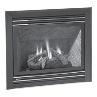
P121/P121LC/P121RC/P131 Zero Clearance Room Sealed Gas Fireplace 15
INSTALLATION
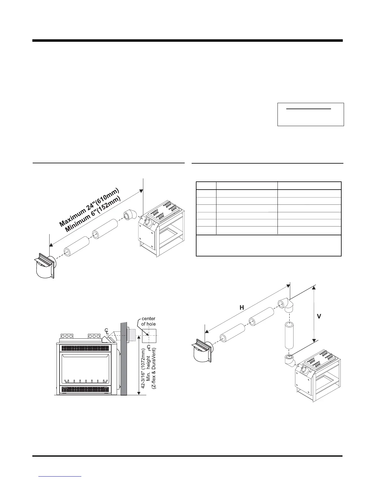
FLUEING ARRANGEMENTS - HORIZONTAL TERMINATIONS
SIMPSON DURA-VENT DIRECT VENT GS SYSTEM (LPG & NG)
The diagram below shows examples of horizontal termination arrangements using one, two, or three 90
o
elbows (two 45
o
elbows equal one 90
o
elbow).
Note:
1) A maximum of three 90
o
elbows are permitted.
2) Minimum distance between elbows is 1 ft. (305mm).
• Maintain clearances to combustibles as listed on page 9.
• Horizontal fl ue must be supported every 3 feet.
• Firestops are required at each fl oor level and whenever passing through a wall.
• Must use optional fl ue adapter (Part# 510-994) when using Simpson Dura-Vent pipe.
• A vent guard should be used whenever the termination is lower than the specifi ed minimum or as per local codes.
Simpson Dura-Vent
4" inner diameter
6-5/8" outer diameter
Straight Out Horizontal Flueing
Horizontal Flueing with One (1) 90
o
Elbow
Option V H
A) 1' (305mm) Minimum 3' (914mm) Maximum
B) 2' (610mm) Minimum 6' (1.86m) Maximum
C) 3' (914mm) Minimum 9' (2.7m) Maximum
D) 4' (1.22m) Minimum 12' (3.6m) Maximum
E) 5' (1.5m) Minimum 15' (4.5m) Maximum
F) 6' (1.86m) Minimum 17' (5.1m) Maximum
Diagram 1
Diagram 2
With the above options, maximum total pipe length if 37 feet with mini-
mum of 6 feet total vertical and maximum 17 feet total horizontal.
Please note minimum 1 foot between 90
o
elbows is required.
Please note the minimum centerline for
basic install shown above.