Regency
®
P121-2/P121LC-2/P121RC-2/P131-2 Zero Clearance Direct Vent Gas Fireplace
16
VENTING ARRANGEMENT - HORIZONTAL TERMINATIONS
Regency
®
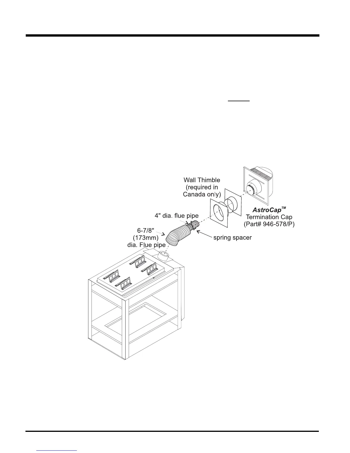
Direct Vent System (Flex) Horizontal Terminations Only
These venting systems, in combination with the P121-2/P121LC-2/P121RC-2/P131-2 Direct Vent Gas Fireplace, have been tested and listed as a
direct vent heater system by Intertek. The location of the termination cap must conform to the requirements in the Vent Terminal Locations diagram
in the "Exterior Vent Termination Locations" section.
Regency
®
Direct Vent (Flex) System Termination Kit (Part# 946-513) includes all the parts needed to install the P121-2/P121LC-2/P121RC-
2/P131-2 with a maximum run of 2 feet. If installing the P121-2/P121LC-2/P121RC-2/P131-2 with a continous vent length of more than 2 ft. (.6m)
to a maximum of 10 ft. (3.0m) use Kit # 946-515 (4 ft.) or 946-516 (10 ft.)
1) 6-7/8" dia. fl exible liner (2 ft. length)
2) 4" dia. fl exible liner (2 ft. length)
3) spring spacers (3)
4) thimble (2)
5) AstroCap termination cap (1)
6) screws (12)
7) tube of Mill Pac (1)
8) plated screws (8)
9) screws #8 x 1-1/2" drill point, stainless steel (4)
Notes:
1) Liner sections should be continuous without any joints or seams.
2) Only Flex pipe purchased from Regency
®
may be used for Flex installations.
3) Regency
®
Direct Vent System (Flex) is only approved for horizontal terminations.
INSTALLATION