10 | Regency
®
U39-10 ULTIMATE Direct Vent Freestanding Gas Stove
|
10
installation
For Vent Termination requirements, see
"Exterior Vent termination Locations" section.
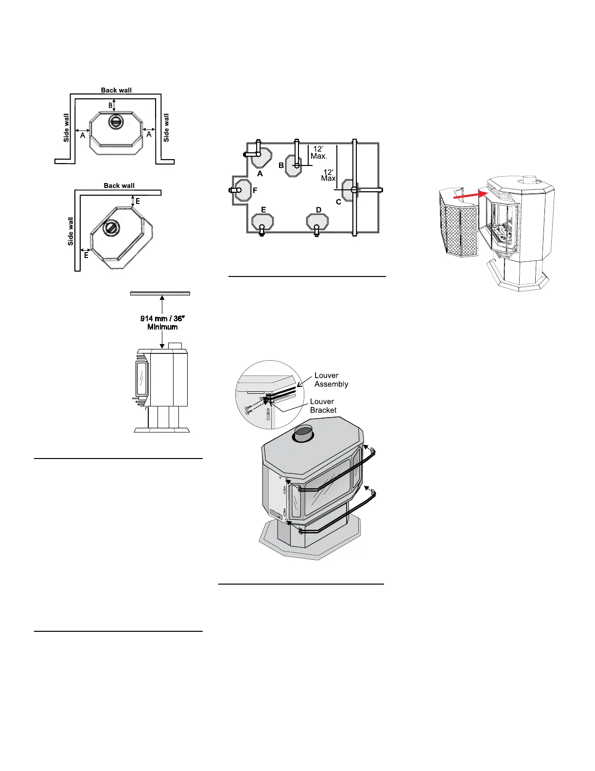
LOUVER
INSTALLATION
1. Attach the top & bottom louvers to the
side stove panel using 2 screws per
side.
MANUFACTURED
MOBILE HOME
ADDITIONAL
REQUIREMENTS
1. Ensure that structural members are not cut or
weakened during installation.
2. Ensure proper grounding using the #8 ground
lug provided.
3. Appliance must be anchored to the oor with
the supplied anchoring methods.
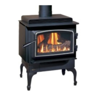
LOCATING YOUR
ULTIMATE GAS STOVE
When selecting a location for your stove, ensure
that the clearances listed above are met as well
as ensuring that there is adequate accessibility for
servicing and proper operation.
A) Cross Corner
B) Room Divider
C) Island
D) Flat on Wall
E) Flat on Wall Corner
F) Flush with Wall/ Alcove
VENTING
INTRODUCTION
The DV Stove Horizontal Vent Kit and the
Simpson Dura-Vent Direct Vent, venting systems,
in combination with the ULTIMATE Direct Vent
Freestanding Gas Stove, U39-NG10, and U39-
LP10, have been tested and listed as direct vent
heater systems by Warnock Hersey/Intertek. If
converting a Class-A Metal Chimney or Masonry
Chimney to a Direct Vent system, see instructions
in "Converting a Class-A Metal Chimney or Masonry
Chimey to a Direct Vent System" section.
These units use the "balanced ue" technology
Co-Axial system. The inner liner vents products
of combustion to the outside while the outer pipe
draws outside combustion air into the combustion
chamber thereby eliminating the need to use heated
room air for combustion and losing warm room air
up the chimney.
Note: These ue pipes must not be connected
to any other appliance.
The gas appliance and vent system must be vented
directly to the outside of the building, and never
be attached to a chimney serving a separate solid
fuel or gas burning appliance. Each direct vent gas
appliance must use it's own separate vent system.
Common vent systems are prohibited.
IMPORTANT
Read all instructions carefully before starting the
installation. Failure to follow these instructions
may create a re or other safety hazard, and will
void the warranty. Be sure to check the venting and
clearance to combustible requirements. Consult your
local building codes before beginning installation.
The location of the termination cap must conform
to the requirements in the "Exterior Vent Terminal
Locations" section.
COMBUSTION AND
VENTILATION AIR
The combustion air from this appliance is drawn
from outside the building through the outer ue.
Extra provision for combustion air inside the
room is not required.
Minimum ceiling
height is 36"/914mm
from top of unit.
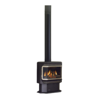
SAFETY SCREEN
INSTALLATION
1. Attach the safety screen over the glass
door.
2. To remove, lift up slightly and pull forward.